
Water leak mitigation system

a technology of water leak detection and water leakage prevention, which is applied in the direction of service pipe systems, functional valve types, instruments, etc., can solve the problems of inability to protect the entire building, inability to use in many applications, and inherently complex current water leak detection devices

Inactive Publication Date: 2006-04-18
FLO GUARD WATER LEAK MITIGATION SYST
View PDF26 Cites 60 Cited by
  • Summary
  • Abstract
  • Description
  • Claims
  • Application Information

AI Technical Summary

Benefits of technology

[0005]The present invention provides for a liquid flow mitigation system comprising a systems interface, a liquid arresting mechanism operable to impede flow of a liquid, a control device operable to produce an input to the systems interface representing a request to impede flow of the liquid, and a liquid utilizing device operable to produce an input to the systems inter

Problems solved by technology

The use of such active monitoring devices makes current water leak detection devices inherently complex and costly.
Due to the complexity and cost of current water leak detection devices, their use is impractical in many applications.
Moreover, these systems are limited either in the ability to protect the entire building, and / or in the ability to provide water flow for important building systems in the event of one or more water leaks.
Consequently, building operations that utilize water to function become inoperable.
When these building devices are not operational, the building is negatively affected.

Method used


Image

  • Water leak mitigation system
  • Water leak mitigation system
  • Water leak mitigation system

Examples


Embodiment Construction

[0012]The following description of the preferred embodiments is merely exemplary in nature and is in no way intended to limit the invention, its application, or uses.

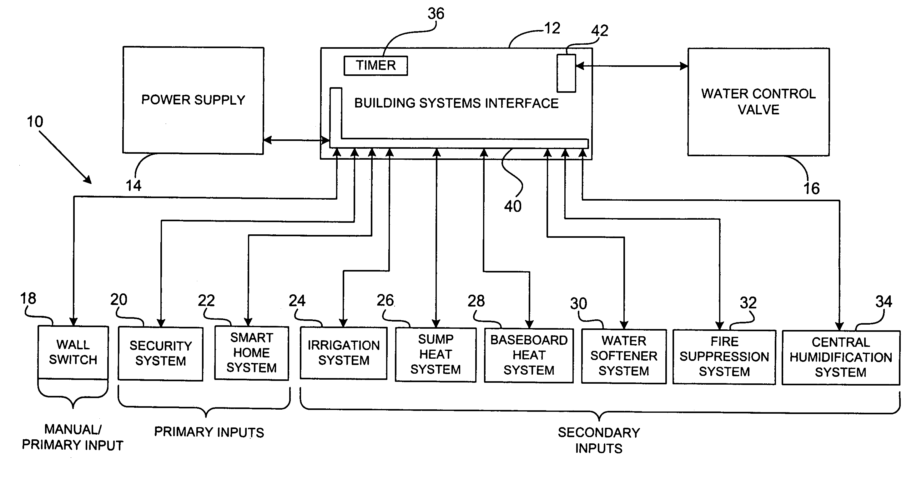
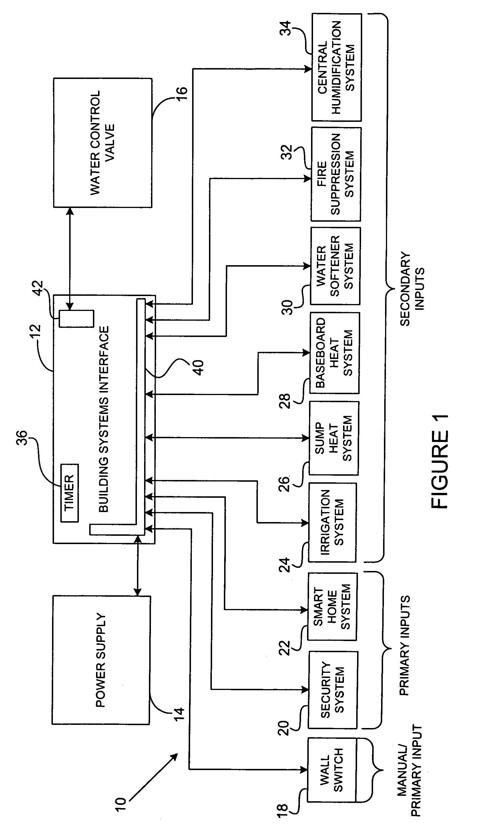
[0013]With reference to FIG. 1, a system for mitigating fluid leaks, such as water leaks for example, is shown at 10. Specifically, the system 10 prevents the flow of water, such as to a building for example, when the system 10 is so set or a particular condition is detected, but resumes water flow when water is required to operate systems or devices that utilize water. The system 10 generally includes an interface, such as a building systems interface 12, a power supply 14, and a plumbing interface or liquid arresting device, such as a water control valve 16. The components of system 10 can be located within a building (not shown), but this is not a requirement. The components of the system 10 can be connected through wiring according to specifications known in the art to, for example, meet local building codes. The in...


PUM


Abstract

A liquid flow mitigation system comprising a systems interface, a liquid arresting mechanism operable to impede flow of a liquid, a control device operable to produce an input to the systems interface representing a request to impede flow of the liquid, and a liquid utilizing device operable to produce an input to the systems interface representing a request for liquid flow. The systems interface directs the liquid arresting mechanism to impede liquid flow when the systems interface is in receipt of an input from the control device. The systems interface directs the liquid arresting mechanism to permit liquid flow when the systems interface is in receipt of an input from the water utilizing device.

Description

CROSS-REFERENCE TO RELATED APPLICATIONS[0001]This application is a continuation-in-part of U.S. patent application Ser. No. 10 / 216,984 filed on Aug. 12, 2002 and issued as U.S. Pat. No. 6,812,848 on Nov. 02, 2004. The disclosure of the above application is incorporated herein by reference.FIELD OF THE INVENTION[0002]The present invention relates to a system capable of controlling the flow of a liquid, such as water. In particular, the present invention relates to a control device capable of restricting water flow in response to an input generated by one or more systems or devices and removing the water flow restriction in response to an input generated by one or more systems or devices that utilize water during operation.BACKGROUND OF THE INVENTION[0003]Water leak detection and control devices capable of restricting water flow to a building in response to the detection of a particular condition, such as one or more water leaks, are known. Current water leak detection and control dev...

Claims


Application Information

Patent Timeline
IPC IPC(8): G08B21/00E03B7/00F17D5/02
CPCF17D5/02E03B7/071Y10T137/1963Y02A20/15
Inventor CANDELA, PAUL JOSEPH
Owner FLO GUARD WATER LEAK MITIGATION SYST
Learn More