Wall and sub-floor water drain panel assembly for basement water-control

a sub-floor and water-control system technology, applied in foundation engineering, protective foundations, constructions, etc., can solve problems such as clogging resistance, drainage capacity in both lateral and longitudinal directions, and narrowing or closing water-escape channels between panels and walls and/or the surface of footings

Inactive Publication Date: 2005-09-15
JANESKY LAWRENCE M
View PDF12 Cites 42 Cited by
  • Summary
  • Abstract
  • Description
  • Claims
  • Application Information

AI Technical Summary

Benefits of technology

[0009] The present invention provides a novel panel strip drainage system to be installed at the wall footing interface around the periphery of a basement room prior to the pouring of a concrete floor thereagainst. The present drainage strip is designed to permit the drainage of water vertically from basement wall cracks and horizontally from wall / footing interfaces into the drain tile system or drain conduit system adjacent the wall footing, to prevent the water from entering the basement room.
[0010] The present drainage strip comprises a vertical strip, such as one molded or extruded from a durable water-resistant plastic molding composition, having a smooth planar interior surface and having an opposed surface provided with stand-offs or spacers forming a water-drainage gap between the opposed surface of the drainage strip and a basement wall. The drainage strip also comprises a lower horizontal drainage section comprising a portion of said vertical strip which is contoured to extend away from the wall / footing interface and to contact the surface of the footing to form a horizontal water drainage conduit section forming a passage open to the wall / footing interface, and which extends longitudinally along the horizontal footing, which is enclosed except at spaced portions thereof which are provided with openings which permit the escape of water from the horizontal passage, out over the surface of the footing and vertically down into the drainage tile or drain conduit or sub-slab aggregate. The spaced portions of the horizontal water drainage conduit section which have drain openings are associated with footing / floor spacer members which communicate with the spaced openings in the horizontal water-drainage conduit section and with the outer edge of the footing to permit the escape of water from the horizontal conduit section outwardly over the footing and into the drain tile or drain conduit. The footing / floor spacer members serve to prevent the wet concrete composition from contacting the surface of the footing in water-flow areas extending from the spaced openings in the horizontal water-drainage conduit and the opposed edges of the footing to prevent the sealing of the openings and the blocking of the water escape from the horizontal water drainage conduit into the drain tile when the basement floor is being poured.

Problems solved by technology

Wall and sub-floor water drain conduit systems are known in the patent literature but most such systems present problems with respect to strength, clog-resistance, drainage capacity in both lateral and longitudinal directions over the footing, and other disadvantages which have limited their use in commercial installations.
Generally, these elongate panels are fabricated of relatively thin plastic which, depending upon design, can become crushed or distorted to some extent under the weight and pressure of the wet concrete composition poured thereagainst when the basement floor is poured over uneven horizontal footing surfaces or over such horizontal surfaces having dried concrete deposits thereon, thereby narrowing or closing the water-escape channels between the panels and the wall and / or the surface of the footing.
The vertical wall-drain panel is intended to be uniformly-spaced from the wall surface by a small distance, such as about 0.4 inch, but panel distortion can result in an uneven spacing, between no space and a spacing or one or more inches.
This presents problems when water escape is blocked or minimized in the lateral direction for any reason.
In U.S. Pat. No. 4,245,443 there is no planar or flat longitudinal upper conduit-free area to permit the concrete floor to be poured smoothly thereagainst, nor is there any planar or linear longitudinal conduit-free area at the discharge edge of the horizontal panel section to prevent or block entry of the wet concrete floor composition into the narrow water-escape conduits during pouring, causing blockage.
More importantly, the system does not allow the flow and escape of water longitudinally along the upper surface of the horizontal footing.

Method used


Image

  • Wall and sub-floor water drain panel assembly for basement water-control
  • Wall and sub-floor water drain panel assembly for basement water-control
  • Wall and sub-floor water drain panel assembly for basement water-control

Examples


Embodiment Construction

(s)

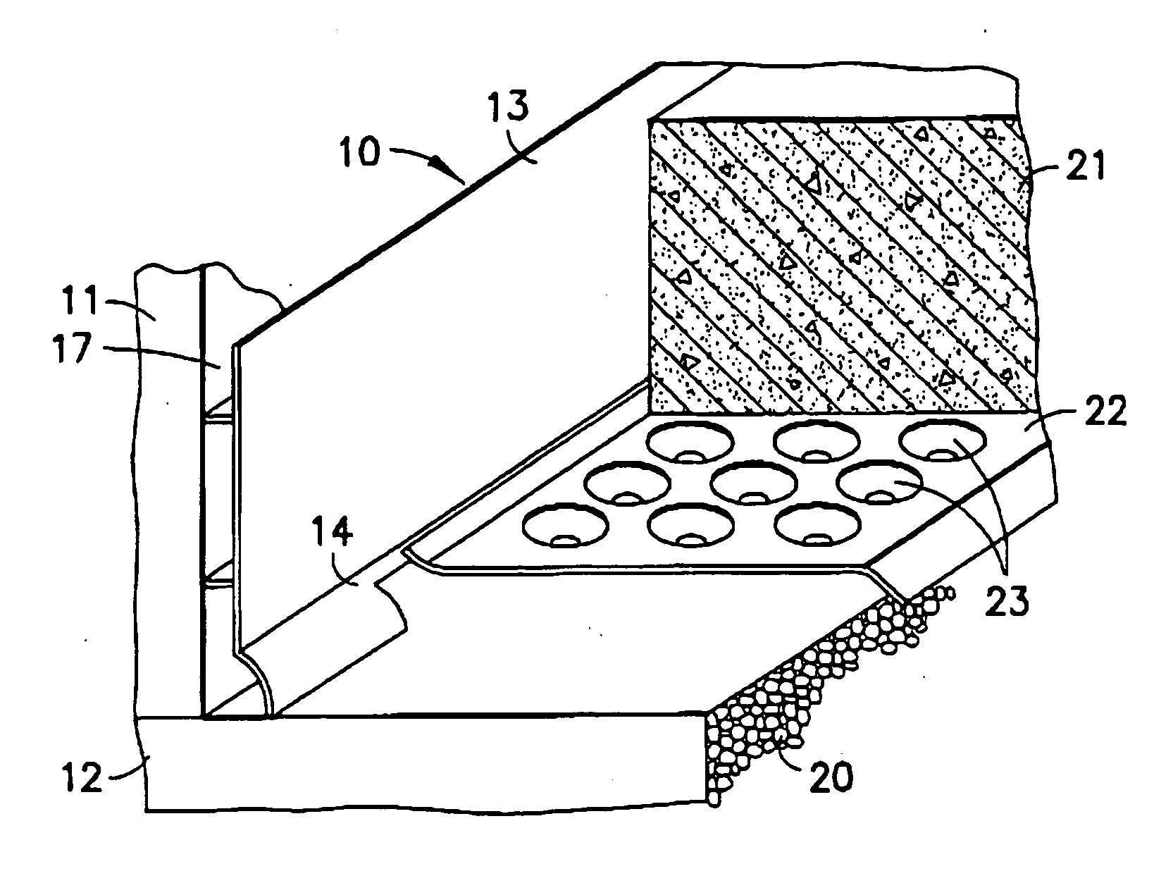
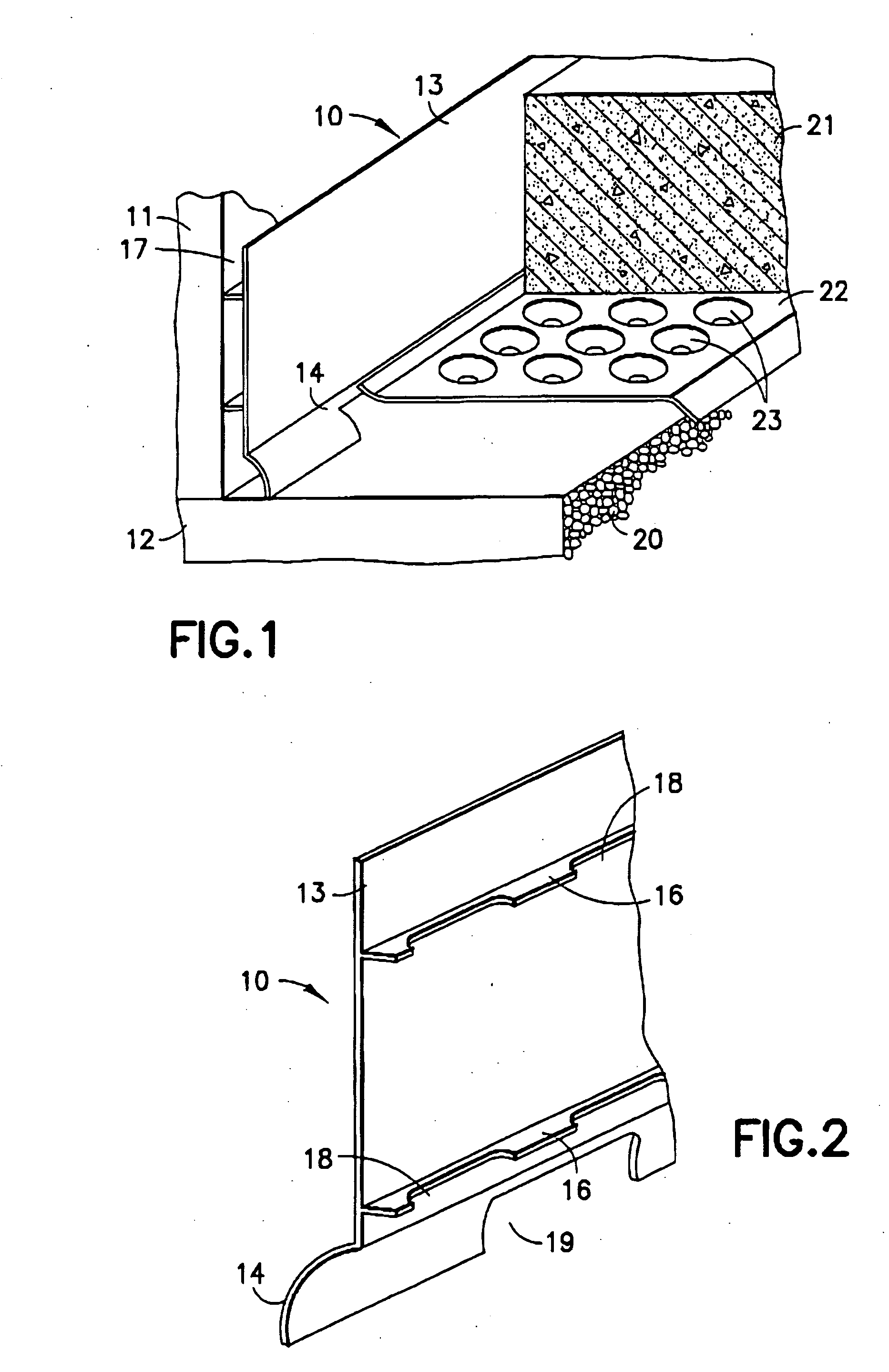
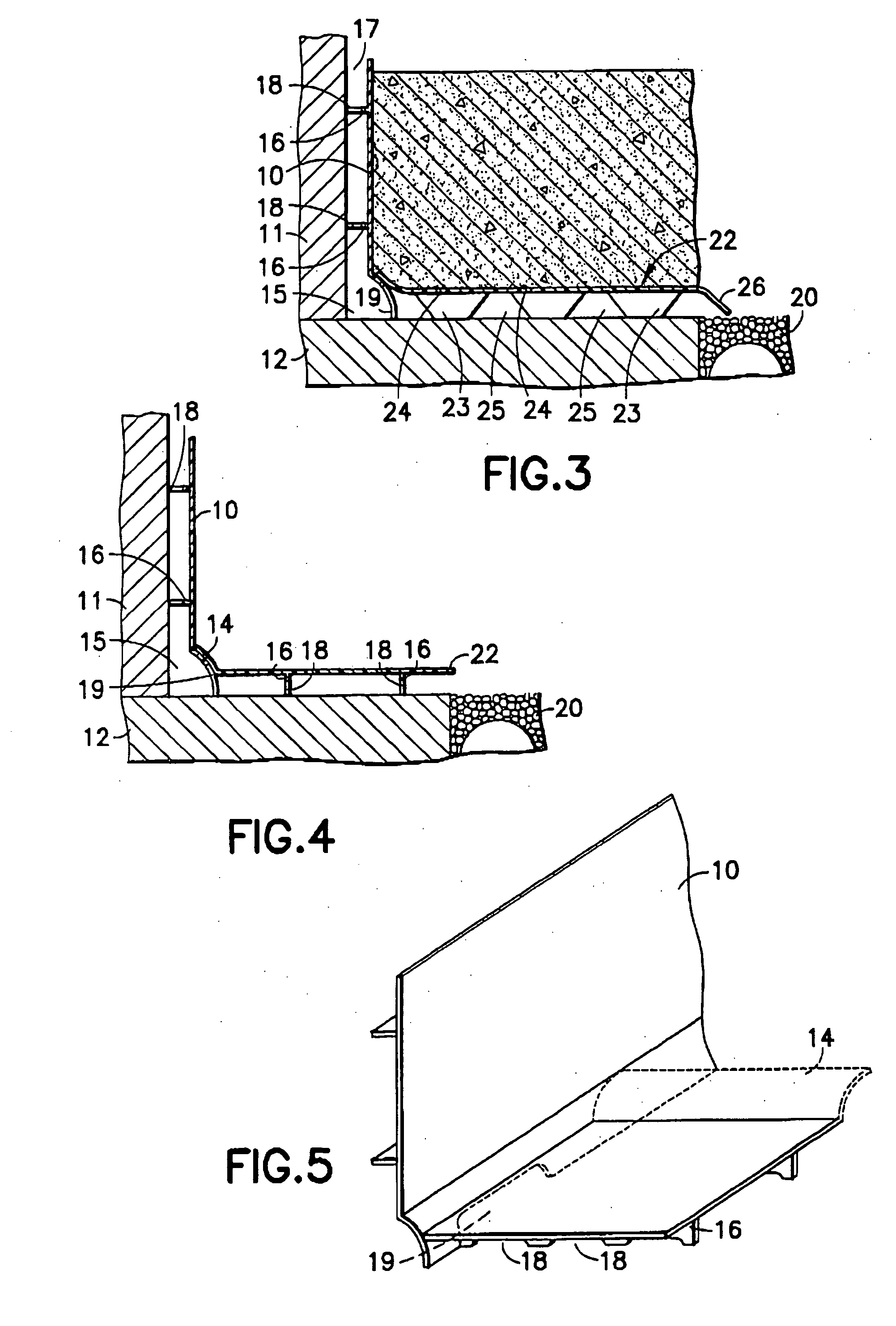
[0017] Referring to FIGS. 1 and 2 of the drawings, the present wall and sub-floor water drain panel 10 is a strong, flexible, semi-rigid panel molded from a suitable plastic composition, such as a polystyrene, polyethylene, polyvinyl chloride, nylon or acrylonitrile-butadiene-styrene polymer (ABS) in a flat shape so as to lay flat against a basement wall 11 and stand on the supporting concrete footing 12 at the wall / footing interface as illustrated by FIGS. 1 and 3. The panel 10 has an upper, vertical wall-engaging section 13 and a lower skirt section 14 which curves or projects outwardly from vertical to form a horizontal water drainage conduit portion 15 adjacent the wall footing interface, which enables water which enters from the interface to be confined and to flow along the length of the footing 12. The drain panel 10 is also provided with or molded with spaced stand-off ribs 16 or spacer ribs which support the panel in spaced position against the surface of the basement wa...


PUM


Abstract

A drain panel assembly for the control of water leaking through a basement wall and/or entering a basement through the interface of a basement wall and a supporting footing. The assembly comprises a plastic drain panel having an upper panel section which extends vertically up from a lower skirt section. The upper panel section is positioned adjacent the basement wall and is closely-spaced therefrom by spacer means which are integral with the rear surface of the upper panel section to admit water running down the basement wall into the lower skirt section. The lower skirt section extends outwardly from the upper panel section and downwardly into contact with the supporting footing section to form a longitudinal water conduit which extends along the length of the footing and is open to the wall/footing interface to receive water therefrom. The water conduit enclosed by the skirt section is provided with a plurality of spaced openings along the footing for draining water therefrom outwardly over the footing into a drain tile.

Description

BACKGROUND OF THE INVENTION [0001] 1. Field of the Invention [0002] The present invention relates to improvements in wall and sub-floor water-control systems for receiving channeling, collecting and expelling ground water from interior basement walls to beneath the floor of the basement and over the footing of basement rooms or other subterranean rooms having walls, wall-supporting footings and a floor. The problems caused by the invasion of ground water into basements and other structures are numerous. Generally such water seeps into basements from the walls and perimeter of the floor at the floor-wall and wall-footing joints, and / or through cracks, due to external hydrostatic pressures of water in the ground. [0003] 2. Brief Description of Related Developments [0004] Wall and sub-floor water drain conduit systems are known in the patent literature but most such systems present problems with respect to strength, clog-resistance, drainage capacity in both lateral and longitudinal di...

Claims


Application Information

Patent Timeline
Patent Type & Authority Applications(United States)
IPC IPC(8): E02D19/00
CPCE02D31/02
Inventor JANESKY, LAWRENCE M.
Owner JANESKY LAWRENCE M
Why Eureka
Try Eureka