Collecting system of core gas in core gas hydrate drilling field

A collection system and hydrate technology, applied in the direction of sampling devices, etc., can solve the problems of large influence of ambient temperature, mixing, low efficiency, etc., achieve the effect of simple and convenient gas sampling process, avoid air mixing, and overcome complex operation

Inactive Publication Date: 2013-07-24
OIL & GAS SURVEY CGS
View PDF4 Cites 9 Cited by
  • Summary
  • Abstract
  • Description
  • Claims
  • Application Information

AI Technical Summary

Problems solved by technology

This method uses normal temperature mechanical oscillation to release gas. The advantages are: simple and fast field operation; the disadvantages are: (1) With the decomposition of hydrate and the release of gas, the pressure in the metal tank is increasing, which inhibits the hydrate. Decomposition, resulting in incomplete gas release; (2) The hydrocarbon gas released from the decomposition is mixed with the air in the reserved space on the top of the metal tank, causing a series of analysis errors
This method adopts natural static release at room temperature, draining water and taking air. The advantage is that the field operation is simple and the influence of air is eliminated; the disadvantages are: (1) The natural release speed is slow; (2) The decomposition and release of the sample is affected by the ambient temperature Larger, resulting in different degrees of hydrate decomposition and larger errors in gas release
[0006] In summary, the above two methods existing in the prior art all have the advantages of simple field operation, but also have the disadvantages of slow decomposition, low efficiency, incompleteness, and being easily affected by ambient temperature, and may also be affected by Effects of Airborne Pollution

Method used


Image

  • Collecting system of core gas in core gas hydrate drilling field
  • Collecting system of core gas in core gas hydrate drilling field

Examples


Embodiment Construction

[0040]The following is a detailed description of the hydrocarbon gas acquisition system in the natural gas hydrate drilling site of the present invention in conjunction with the accompanying drawings, so that those skilled in the art can understand the solution of the present invention more clearly, but it does not limit the protection of the present invention. scope.

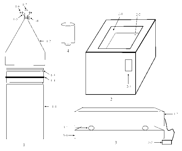
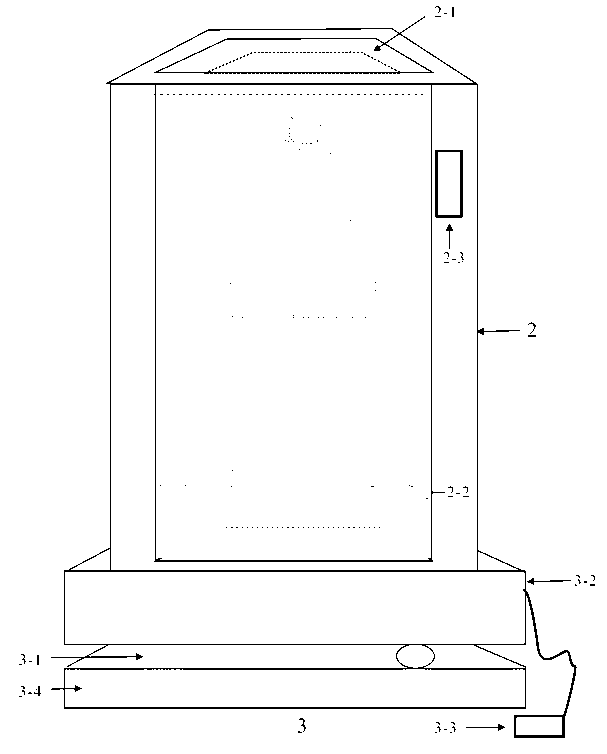
[0041] as attached figure 1 As shown, the hydrocarbon gas collection system in the natural gas hydrate drilling site of the present invention generally includes four parts: a gas collection tank 1, a water bath constant temperature box 2, a shaking table 3 and a gas collection bottle 4 ( figure 1 ). Wherein, the gas collecting tank 1 comprises a tank body 1-1, a tank body cover 1-2, a sealing ring slot 1-3, a sealing ring 1-4, a gas collecting bottle bracket 1-5, a fixing screw 1-6, Gas collection conduit 1-7, gas collection conduit switch 1-8; water bath constant temperature box 2 specifically includes water...


PUM


Abstract

The invention provides a collecting system of core gas in a natural gas hydrate drilling field. The collecting system comprises an air collector, a water bath thermotank, a vibration table and a gas collecting bottle, wherein the water bath thermotank is arranged on the vibration table; the air collector comprises a tank body and a tank body cover, wherein the tank body and the tank body cover are separable, and the tank boy is in seal connection with the tank body cover; and when the collecting system is adopted to collect the core gas, the tank body filled with a core sample is in seal connection with the tank body cover when the water bath thermotank is positioned in a constant temperature saturated salt water environment, and the gas collecting bottle is connected with a gas collecting outlet of the tank body cover under the constant temperature saturated salt water environment. The collecting system provided by the invention has the advantages that the processes of packaging the aquo-complex core sample, releasing the gas, collecting the gas, collecting gas in an oscillation manner and sealing and storing the gas are finished once, a series of pilot processes are simplified, and the work efficiency of gas collection is greatly improved.

Description

technical field [0001] The invention relates to the field of gas collection, and more specifically to a system for quickly collecting hydrocarbon gas in rock cores (and hydrates) at the drilling site of natural gas hydrate. Background technique [0002] Gas hydrate is a kind of high density (1 m 3 Can release 164 m 3 The clean energy of methane) is twice the sum of conventional energy resources such as coal, oil, and natural gas in the world, and has attracted great attention from many countries around the world. During the drilling process, the amount of gas released by the core is one of the key parameters for quickly judging the presence or absence of hydrates on site. Therefore, the on-site rapid gas recovery device for hydrate drilling cores is an important basic equipment for gas collection, measurement, and rapid identification of hydrates at the drilling site. [0003] According to the literature search, at present, the core gas collection methods for natural gas ...

Claims


Application Information

Patent Timeline
Patent Type & Authority Applications(China)
IPC IPC(8): G01N1/22
Inventor 赵省民邓坚饶竹陆程苗忠英刘晨
Owner OIL & GAS SURVEY CGS
Why Eureka
Try Eureka