Telecommunication network synchronization

a technology of telecommunication network and synchronisation process, which is applied in the direction of data switching network, frequency-division multiplex, instruments, etc., can solve the problems of reducing the overall time taken to synchronise the network, and achieve the effect of fast stabilisation of the network synchronisation process and mitiging the disadvantages of known synchronisation network

Inactive Publication Date: 2006-04-18
TELEFON AB LM ERICSSON (PUBL)
View PDF21 Cites 40 Cited by
  • Summary
  • Abstract
  • Description
  • Claims
  • Application Information

AI Technical Summary

Benefits of technology

[0009]It is an object of the present invention to overcome or at least mitigate the disadvantages of known synchronisation networks. In particular, it is an object of the present invention to provide a synchronisation network in which synchronisation problems may be overcome substantially on a node level, automatically and with no or minimal operator intervention. It is a second object of the present invention to allow for the fast stabilisation of a network synchronisation process. It is a third object of the present invention to allow newly introduced network nodes to be rapidly synchronised with the network.
[0014]Embodiments of the present invention allow a node to compare the merits of different incoming data links as sources of synchronisation information. In the event that synchronisation (or re-synchronisation) is required, the node may select that incoming link having an attribute indicating the shortest path length from the master node. The introduction of a delay in the propagation of messages at at least certain nodes, increases the probability that a synchronisation message will be received first at a given node over a shorter path, rather than over a longer path. This will tend to decrease the overall time taken to synchronise the network.
[0020]The delay to be introduced by a node may be incorporated into a Synchronisation Status Message. This avoids the need to have delay tables at all network nodes. However, in the alternative, delay tables may be present at all nodes.

Problems solved by technology

This will tend to decrease the overall time taken to synchronise the network.

Method used


Image

  • Telecommunication network synchronization
  • Telecommunication network synchronization
  • Telecommunication network synchronization

Examples


Embodiment Construction

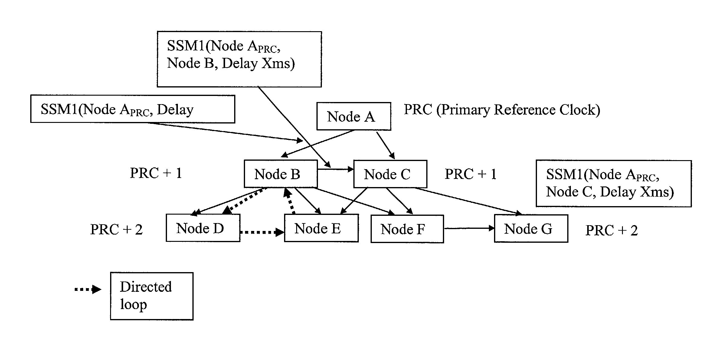
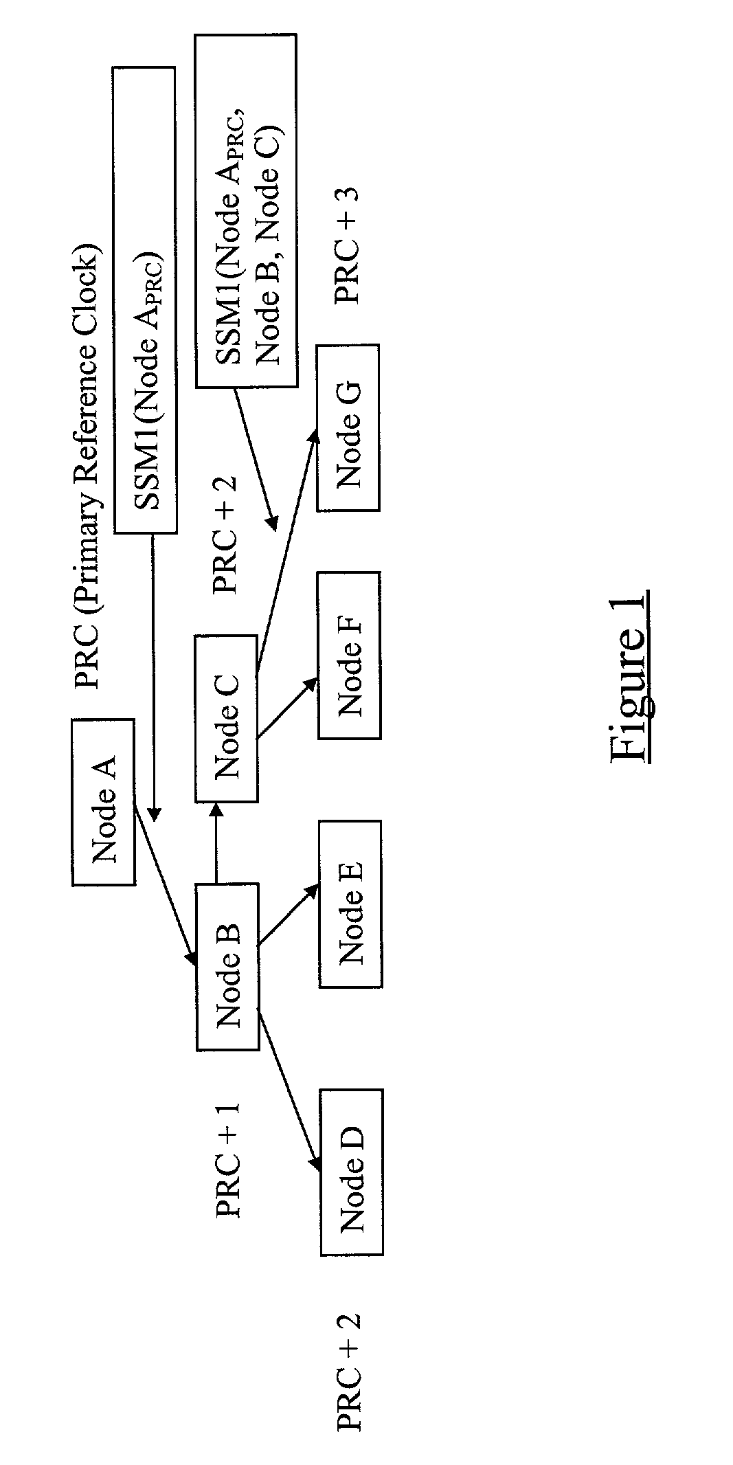
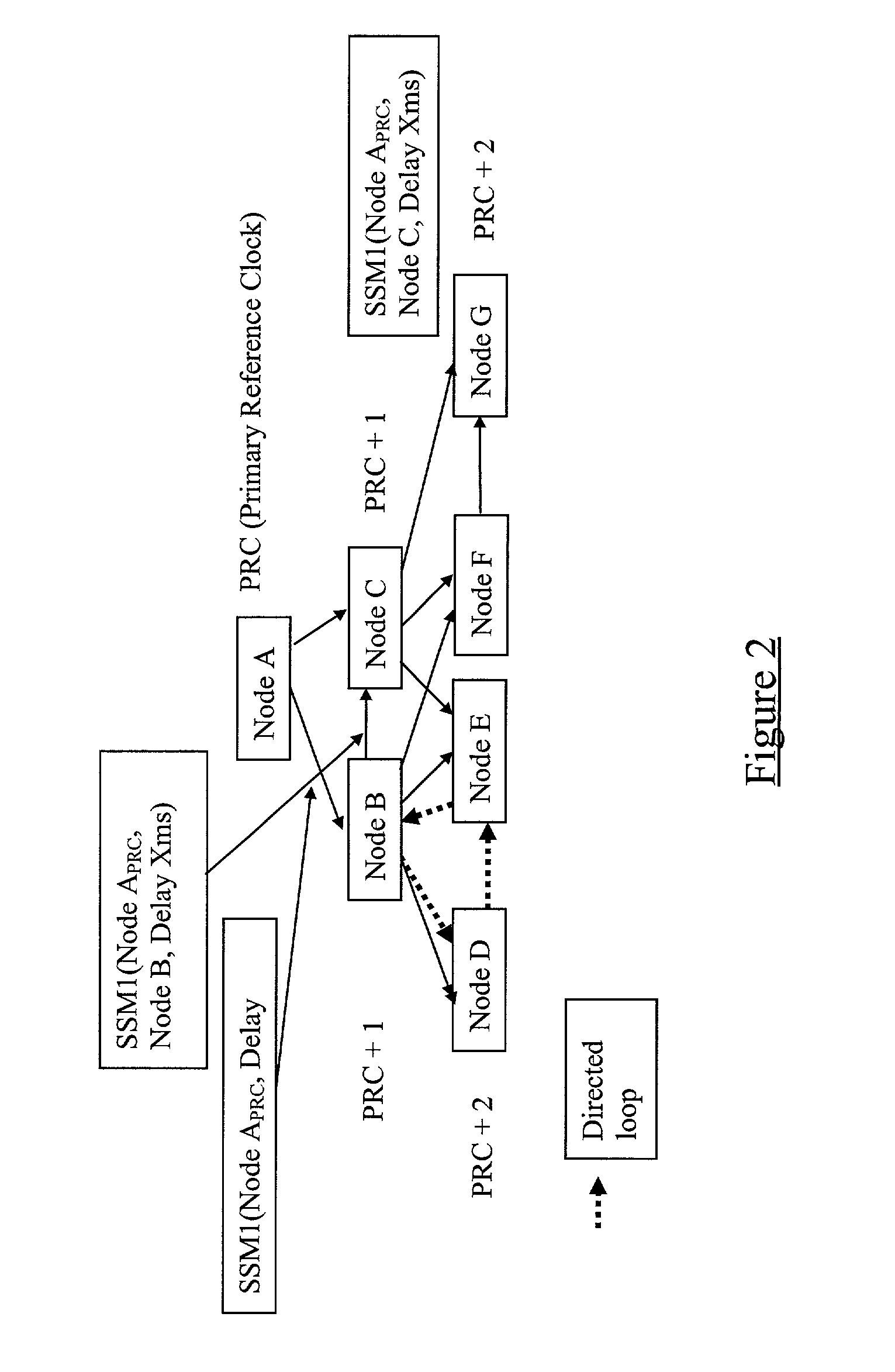
[0066]There is illustrated in FIG. 1 a multi-node telecommunication network comprising Nodes A to G. The Nodes are interconnected by data links which may carry user data, signalling data, or a combination of both. In one example, the network of FIG. 1 might be a UMTS Terrestrial Radio Access Network (UTRAN), where certain of the nodes (for example Node A) might be Radio Network Controllers (RNCs) whilst others of the nodes (for example Nodes B to G) might be Radio Base Stations (RBSs).

[0067]Node A is a so-called “master Node” and is connected to a Primary Reference Clock (PRC). As has already been outlined above, the slave Nodes B to G are able to synchronise with another network Node (and hence with the network as a whole) using data signals received on an incoming data links. The accuracy of the synchronisation will depend to a large extent upon the remoteness of the node which is being synchronised from the master node. An important consideration therefore in choosing which incom...


PUM


Abstract

A method of synchronizing nodes of a telecommunication network in which a master node is coupled to a Primary Reference Clock (PRC) and a plurality of slave nodes are each arranged to synchronize their internal clocks to the PRC using data received on incoming data links. The method includes propagating Synchronization Status Messages through the network from the master node, with each node through which a message passes incorporating into the message its own identity, thereby generating in each message a node path which has been followed by the message. For each incoming link of each node, the path or path length of a Synchronization Status Message received on that link is registered as an attribute for that link.

Description

FIELD OF THE INVENTION[0001]The present invention relates to the synchronisation of nodes in a telecommunication network and in particular, though not necessarily, to the synchronisation of nodes in a Universal Mobile Telecommunications System network.BACKGROUND TO THE INVENTION[0002]In a digital communication network, such as a telecommunications network or a private network having several private branch exchanges, it is often necessary to synchronise the time clocks of respective network nodes in order to ensure correct operation of the network. Network synchronisation permits all nodes on the network to operate from a common time base. This means that when one node (i.e. an intersection point) sends data to another node, both nodes can be expected to operate at approximately the same rate ensuring the successful transfer of data between the nodes. Background information on the need for network node synchronisation can be found in EP0450828.[0003]In so-called “master-slave” synchr...

Claims


Application Information

Patent Timeline
Patent Type & Authority Patents(United States)
IPC IPC(8): H04L12/28H04J3/06H04L7/00H04Q11/04
CPCH04J3/0679H04J2203/0089
Inventor LIPSANEN, MIKKO ANTERO
Owner TELEFON AB LM ERICSSON (PUBL)
Why Eureka
Try Eureka