Electrical switchgear apparatus comprising an arc extinguishing chamber equipped with deionizing fins

a switchgear and arc extinguishing technology, which is applied in the direction of circuit-breaking switches, circuit-breaking switches for excess currents, high-tension/heavy-dress switches, etc., can solve the problems of increased chamber size, increased complexity, and high cost of such apparatuses compared to conventional apparatuses

Inactive Publication Date: 2004-09-21
SCHNEIDER ELECTRIC IND SAS
View PDF16 Cites 27 Cited by
  • Summary
  • Abstract
  • Description
  • Claims
  • Application Information

AI Technical Summary

Benefits of technology

The gulley and the stack enable the arc to establish itself quickly and stably at the back of the chamber, in the zone which presents an oblong shape in cross-section. It is known that in an open environment the arc naturally tends to take a general cylindrical shape of circular cross-section. The oblong shape of the stack therefore contributes to a large constriction of the arc, and therefore to a large energy exchange with the fins and the walls at this level. A gas convection current is established between the fins, laterally with respect to the gulley, and enables cooling and de-ionization of the gases to take place in contact with the fins until the arc has been extinguished. This fast cooling of the gases considerably limits the pressure increase in the chamber. The external manifestations are therefore considerably reduced or even totally eliminated. The surface of the fins is used throughout breaking and ensures a very good efficiency in the energy transfer. It should be emphasized that the flat surfaces of the fins are used more to absorb the heat of the gases emitted than to interact directly with the arc. More precisely, the arc does not seem to divide into a multiplicity of arcs drawn in series between adjacent fins.
Preferably, the switchgear apparatus is a limiting circuit breaker comprising rigid input conductors for conveying current to the contacts, these rigid conductors being shaped in such a way that, when a current flows therethrough, they generate an intense electromagnetic field near the contacts, such as to cause electromagnetic repulsion of the movable contact to the separated position and to project the electric arc into the chamber. Typically, the stationary contact is supported by a U-shaped conductor. Other shapes amply described in the state of the art can however be envisaged. Projection of the arc enables the latter to reach the stack rapidly.

Problems solved by technology

Moreover, the gases outlet from the unit can be considered to be polluting and therefore have to be filtered.
Furthermore, the cost of such apparatuses as compared to conventional apparatuses is very high, which results in their only being implemented under extreme conditions, for example in explosive environments.
However, the size of the chamber necessary to achieve high breaking performances is thereby increased as the energy absorption capacity of the fins is not fully used due to the rapid progression of the arc.
Furthermore, the recirculation channel makes the case more bulky and more complex.
However, the flow of the arc gives rise to periodic restrikings of the arc on the contacts, which damage the contacts.
The lateral part of the plates is therefore not used efficiently for cooling the arc.
Finally, the treatment of the plates in several layers of different materials increases the cost of the device considerably.

Method used


Image

  • Electrical switchgear apparatus comprising an arc extinguishing chamber equipped with deionizing fins
  • Electrical switchgear apparatus comprising an arc extinguishing chamber equipped with deionizing fins
  • Electrical switchgear apparatus comprising an arc extinguishing chamber equipped with deionizing fins

Examples


third embodiment

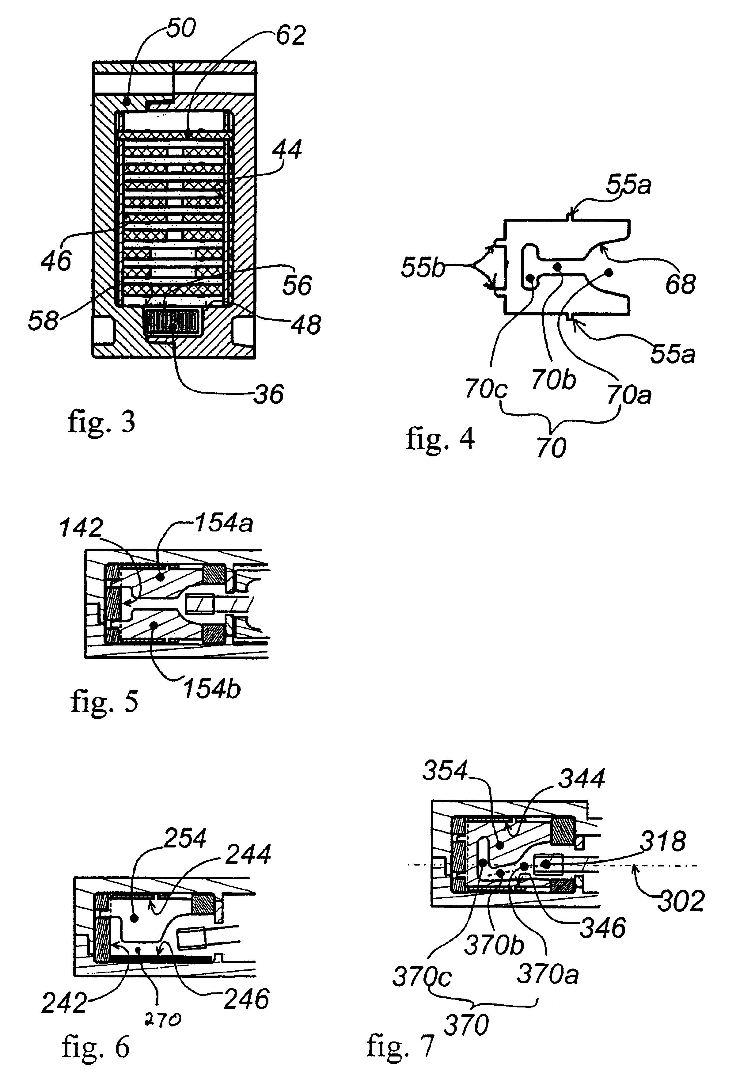
the invention, illustrated in FIG. 6, was therefore specifically developed for an apparatus of small width equipped with a narrow arc extinguishing chamber. The gulley 270 runs directly along one of the side walls 246 and is bounded on the opposite lateral side by fins 254 pressed against the side wall 244. The width of the fins, measured between the gulley 270 and the wall 244, is then sufficient for the side walls not to significantly hinder penetration of the gases between the fins 254. Tests show that the gases do actually penetrate between the fins 254 and are cooled there. However, direct exposure of the wall 246 to the arc makes this device delicate to master and imposes a non gas-generating wall with a good heating capacity, for example made of porous ceramic.

fourth embodiment

the invention, also developed for narrow chambers, is illustrated in FIG. 7 and solves this residual problem. In the figure, the reference signs used in the first embodiment have been used as far as possible for parts corresponding to similar parts of the first embodiment, with the FIG. 3 added in front. To describe this embodiment in detail, a mid-plane 302 of the chamber, situated mid-way from the side walls 344, 346 of the chamber, will be taken as geometric reference. The contacts 318 are situated offset laterally with respect to the mid-plane 302. The separators 354 are cut so as to define a gulley 370 comprising a mouth 370a, a middle part 370b and a bend part 370c. The middle part 370b extends obliquely with respect to the mid-plane. Thus, the gulley 370 is moved to be located closer to one of the side wall moving away from the opening volume 338. Between the middle part of the gulley 370b and the wall 344, the fins are of small width, whereas on the other side of the gulley ...


PUM


Abstract

A circuit breaker comprises a pair of separable contacts arranged in an opening volume. A plurality of flat de-ionization fins are arranged inside an arc extinguishing chamber opening out onto the opening volume. The chamber is bounded by two opposite side walls, a rear wall located away from the opening volume, a bottom wall and a top wall. Each fin has a free attack edge exposed to the arc. The free edges of the fins laterally bound a longitudinal gulley extending in a heightwise direction from the bottom electrode to the top wall, and longitudinally from a first longitudinal end opening out onto the opening volume at a second longitudinal end tapering to form a stack near to the rear wall, passing via a narrow intermediate portion. A bottom longitudinal electrode partially covers the bottom wall and extends longitudinally facing the gulley at least from the second contact up to the stack.

Description

The invention relates to an electrical switchgear apparatus, in particular a current limiting apparatus such as a current limiting circuit breaker, the external manifestations whereof when breaking is performed are reduced or even non-existent.STATE OF THE ARTIn the document FR 2,589,624 a conventional arc extinguishing chamber for a low-voltage power circuit breaker is described. The chamber is situated facing the separable contacts of the circuit breaker and is provided with gas outlet orifices on a rear wall opposite from the contacts. Flat metal fins are arranged inside the chamber, between the contacts and the gas outlet orifice, perpendicularly to the side walls. In the event of a short-circuit occurring, separation of the contacts gives rise to an electric arc which is projected into the chamber by an electromagnetic loop effect. As it progresses in the chamber, the arc encounters the fins which absorb a part of its energy. The arc also exchanges heat with the side walls of t...

Claims


Application Information

Patent Timeline
Patent Type & Authority Patents(United States)
IPC IPC(8): H01H9/34H01H9/30
CPCH01H1/2058H01H9/34H01H9/346
Inventor CHARLES, RICHARDDYE, STEPHANEMOREAU, LUC
Owner SCHNEIDER ELECTRIC IND SAS
Why Eureka
Try Eureka