Optical receiving apparatus and method for controlling the optical receiving apparatus

a technology of optical receiving apparatus and optical receiving device, which is applied in the direction of optical elements, multiplex communication, instruments, etc., can solve the problems of difficult to quickly stabilize the control amount in the delay interferometer, dispersion compensator, and difficulty in both after quick stabilization, so as to achieve quick stabilization the effect of controls

Inactive Publication Date: 2009-01-13
FUJITSU LTD
View PDF19 Cites 26 Cited by
  • Summary
  • Abstract
  • Description
  • Claims
  • Application Information

AI Technical Summary

Benefits of technology

[0038]In the light of the above problem, an object of the present invention is to set simultaneously the delay interferometer and the variable chromatic dispersion compensator in the optical receiving apparatus, efficiently and optimally, at the time of the initial start (at the time of a start of the system operation, protection and path switching) and during the system operation.
[0045]The present invention further provides an optical receiving apparatus for performing a receiving process on an optical signal undergone differential M-ary phase modulation in which M=2n where n is a natural number, the optical receiving apparatus comprising a variable dispersion compensation unit for variably performing dispersion compensation on the received optical signal, a delay interference unit for performing a delay interference process on the optical signal from the variable dispersion compensation unit, a photoelectric conversion detecting unit for performing photoelectric conversion detection on the optical signal from the delay interference unit to output a demodulated electric signal demodulated from the differential M-ary phase modulated optical signal, an error monitor for detecting the number of errors from the demodulated electric signal fed from the photoelectric conversion detecting unit, a first dispersion compensation controlling unit for controlling the variable dispersion compensation unit to roughly adjust a dispersion compensation amount in the variable dispersion compensation unit when an operation of the optical receiving apparatus is started so that the number of errors detected by the error monitor is below a predetermined value, a first phase controlling unit for roughly adjusting an optical phase control amount in the delay interference unit in association with the adjustment of the dispersion compensation amount performed by the first dispersion compensation controlling unit, a second phase controlling unit for performing a control to stabilize the optical phase control amount in the delay interference unit on the basis of the demodulated electric signal from the photoelectric conversion detecting unit when the number of errors is below the predetermined value, and a second dispersion compensation controlling unit for performing a control on the dispersion compensation amount in the variable dispersion compensation unit after the optical phase control by the second phase controlling unit is started so that the number of errors is minimum.
[0047]The present invention still further provides a method for controlling an optical receiving apparatus for performing a receiving process on an optical signal undergone differential M-ary phase modulation in which M=2n where n is a natural number, the optical receiving apparatus comprising a variable dispersion compensation unit for variably performing dispersion compensation on the received optical signal, a delay interference unit for performing a delay interference process to make one branched component delayed by one bit of the optical signal from the variable dispersion compensation unit and the other branched component undergone an optical phase control of the same interfere with each other, a photoelectric conversion detecting unit for performing photoelectric conversion detection on the optical signal from the delay interference unit to output a demodulated electric signal demodulated from the differential M-ary phase modulated optical signal, and an error monitor for detecting the number of errors from the demodulated electric signal fed from the photoelectric conversion detecting unit, the method comprising the steps of adjusting roughly a dispersion compensation amount in the variable dispersion compensation unit and an optical phase control amount in the delay interference unit so that the number of errors detected by the error monitor is below a predetermined value, starting a control to stabilize the optical phase control amount in the delay interference unit on the basis of the demodulated electric signal from the photoelectric conversion detecting unit when the number of errors is below the predetermined value, and starting a control on the dispersion compensation amount in the variable dispersion compensation unit so that the number of errors is minimum.
[0049]Accordingly, the present invention can provide an advantage that the dispersion compensation controlling unit can set, efficiently and optimally, the variable dispersion compensation unit in the optical receiving apparatus at the time of the initial setting (at the time of a start of the system operation, protection and path switching) and during the system operation. Further, when the delay interference controlling unit for controlling the phase control amount in the delay interference unit is provided, it is possible to quickly stabilize the controls by the delay interference controlling unit and the dispersion compensation controlling unit.

Problems solved by technology

For this, there is a problem that a long time is required to search optimum control amounts for both the delay interferometer and the variable dispersion compensator to obtain good quality of the received signal, which is harm to quickly stabilize the control amounts in the delay interferometer and the variable dispersion compensator.
Namely, since the number of errors above mentioned varies according to the optical phase control by the delay interferometer and the control on the dispersion compensation amount by the variable dispersion compensator, it is difficult to quickly stabilize the control amounts in the both after the initial start of the apparatus.

Method used


Image

  • Optical receiving apparatus and method for controlling the optical receiving apparatus
  • Optical receiving apparatus and method for controlling the optical receiving apparatus
  • Optical receiving apparatus and method for controlling the optical receiving apparatus

Examples


first embodiment

[A] Description of First Embodiment

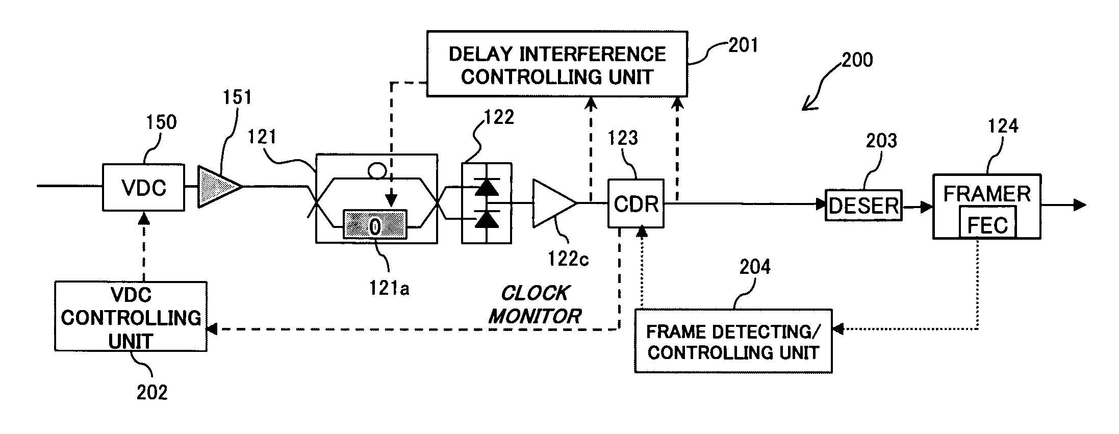
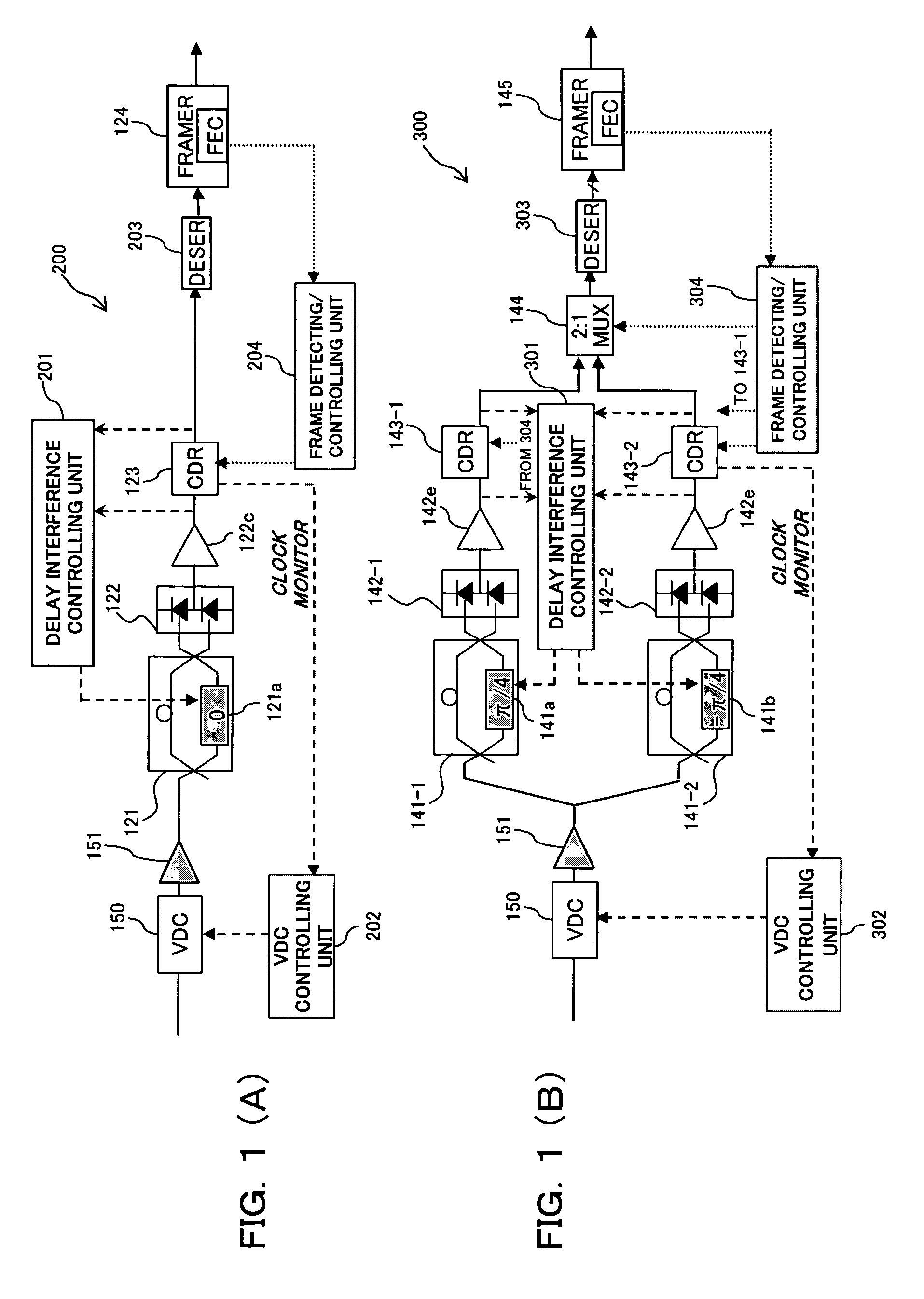
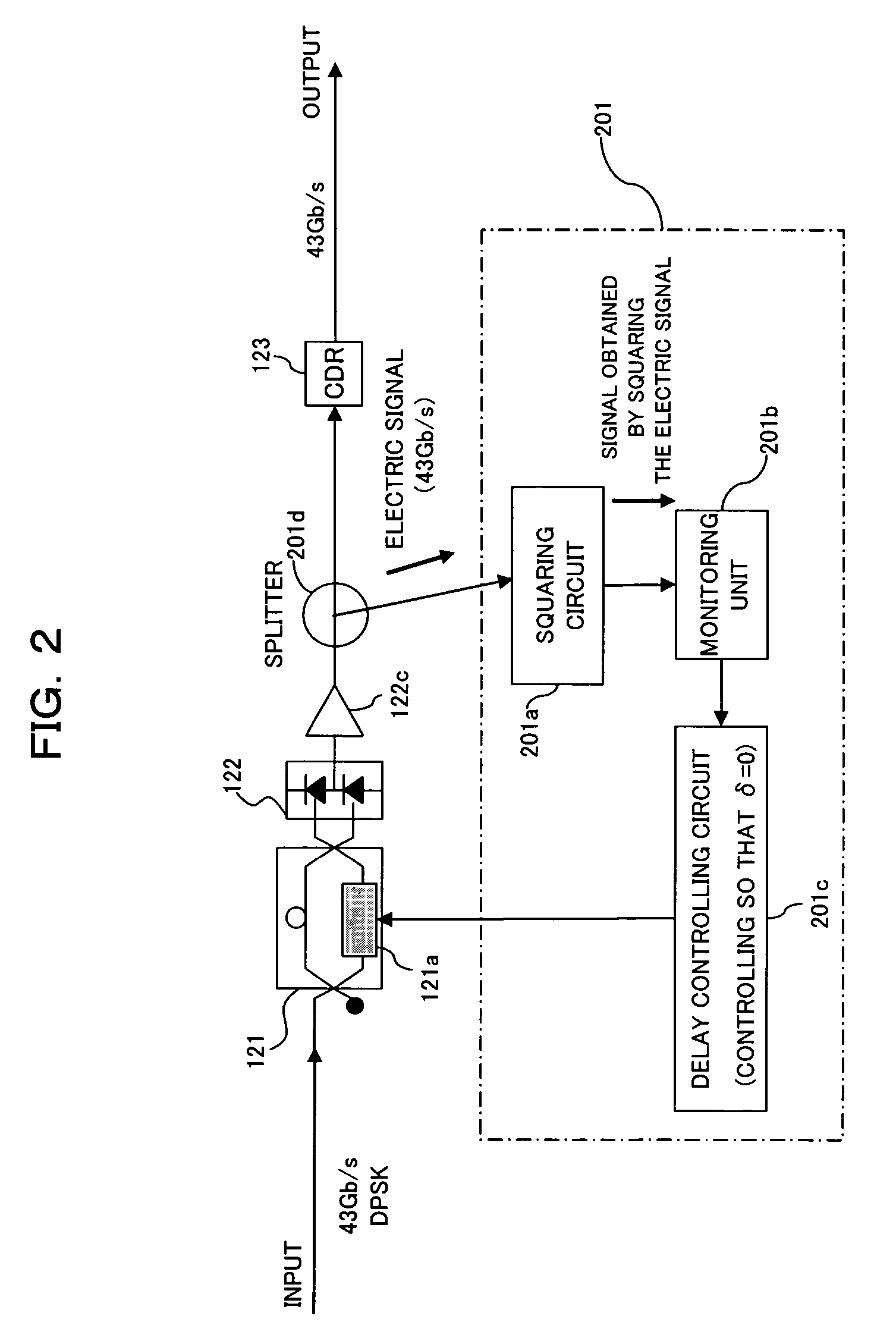
[0068]FIGS. 1(A) and 1(B) are diagrams showing optical receiving apparatuses 200 and 300 according to a first embodiment of this invention. The optical receiving apparatus 200 shown in FIG. 1(A) adopts (CS)RZ-DPSK modulation / demodulation system, which is differential binary phase modulation. The optical receiving apparatus 200 is an improvement of the above-mentioned optical receiving apparatus 120 shown in FIG. 30. The optical receiving apparatus 300 shown in FIG. 1(B) adopts (CS)RZ-DQPSK modulation / demodulation system, which is differential quaternary phase modulation. The optical receiving apparatus 300 is an improvement of the above-mentioned optical receiving apparatus 140 shown in FIG. 31.

[0069]Like the delay interferometer 121 of the optical receiving apparatus 120 shown in FIG. 30, a delay interferometer 121 of the optical receiving apparatus 200 shown in FIG. 1(A) is a delay interference unit for performing a delay interference process on ...

second embodiment

[B] Description of Second Embodiment

[0125]FIGS. 26(A) and 26(B) are block diagrams showing optical receiving apparatuses 210 and 310 according to a second embodiment of this invention. The optical receiving apparatus 210 shown in FIG. 26(A) adopts (CS)RZ-DPSK modulation / demodulation system, which is differential binary phase modulation. The optical receiving apparatus 210 is characterized by a control sequence for setting the dispersion compensation amount in a VDC 150, and a control sequence for setting the phase control amount in a delay interferometer 121.

[0126]The optical receiving apparatus 310 shown in FIG. 26(B) adopts (CS)RZ-DQPSK modulation / demodulation system, which is differential quaternary phase modulation. The optical receiving apparatus 310 is characterized by a control sequence for setting the dispersion compensation amount in a VDC 150 and a control sequence for setting the phase control amount in delay interferometers 141-1 and 141-2. Incidentally, like reference c...


PUM


Abstract

An optical receiving apparatus sets, efficiently and optimally, a delay interferometer and a variable wavelength dispersion compensator in the apparatus. The apparatus has a variable dispersion compensation unit performing variably dispersion compensation on a received optical signal, a delay interference unit performing a delay interference process on the optical signal from the variable dispersion compensation unit, a photoelectric conversion detecting unit performing photoelectric conversion detection on the optical signal from the delay interference unit and outputting an electric signal demodulated from the differential M-ary phase modulated optical signal, a clock signal extracting unit extracting a clock signal from the demodulated electric signal fed from the photoelectric conversion detecting unit, and a dispersion compensation controlling unit controlling a dispersion compensation amount in the variable dispersion compensation unit on the basis of the clock signal extracted by the clock signal extracting unit.

Description

BACKGROUND OF THE INVENTION[0001]1) Field of the Invention[0002]The present invention relates to an optical receiving apparatus and a method for controlling the optical receiving apparatus suitable for use in an optical transmission system, particularly, an optical transmission system adopting optical phase modulation and demodulation.[0003]2) Background of the Invention[0004]In these years, there is a growing demand for introduction of a 40 Gbit / s optical transmission system in the next generation. In addition, a transmission distance and frequency utilization efficiency equivalent to those of the 10 Gbit / s system are also demanded. RZ-DPSK (Differential Phase Shift Keying) or CSRZ-DPSK, which has excellent optical signal-to-noise ratio (OSNR) tolerance and nonlinearity tolerance as compared with NRZ (Non Return to Zero) employed in known systems of not larger than 10 Gb / s, is being vitally researched and developed as a means meeting the above demands. Besides the above modulation ...

Claims


Application Information

Patent Timeline
Patent Type & Authority Patents(United States)
IPC IPC(8): H04B10/00H04B10/2507H04B10/07H04B10/2513H04B10/516H04B10/548H04B10/588H04B10/61
CPCH04B10/66
Inventor OOI, HIROKIMIURA, AKIRAHOSHIDA, TAKESHI
Owner FUJITSU LTD
Why Eureka
Try Eureka