Articulated high density fiber optic splice and termination shelf

a high-density fiber optic splice and termination technology, applied in the field of shelves, can solve the problems of reducing the available rack space, pigtails and exiting jumper fibers, and reducing the space with a “rat's nest” effect, and achieve the effect of easy work

Active Publication Date: 2006-04-18
COMMSCOPE INC
View PDF15 Cites 127 Cited by
  • Summary
  • Abstract
  • Description
  • Claims
  • Application Information

AI Technical Summary

Benefits of technology

[0006]The present invention is directed to a shelf that can be stored within a rack or cabinet for providing access to items residing inside the shelf. The shelf includes: a main panel unit; a slide member; and a component mounting panel. The slide member is pivotally attached to the main panel unit for pivotal movement about a first pivot axis and is configured for slidable mounting relative to an enclosure such that the main panel unit can be moved from a retracted position within the enclosure to an extended position that is forward of the enclosure. The main panel unit is pivotable relative to the slide member between a raised position and a lowered position when extended forwardly of the enclosure. The component mounting panel is pivotally mounted to the main panel unit for pivotal movement about a second pivot axis between front access and rear access positions such that a front surface of the component mounting panel can be accessed from a forward work location when the component mounting panel is in the front access position, and a rear surface of the component mounting plate can be accessed from a forward work location when the component mounting plate is in its rear access position. This configuration can enable the mounting of components (such as splice site carriers and termination site devices) on the same shelf in great density while still enabling an operator to work easily on components mounted on the shelf from a location forward of the shelf.

Problems solved by technology

Of course, housing the splicing and termination sites on different shelves can complicate or disorganize the distribution of OSP cables, pigtails and exiting jumper fibers while simultaneously reducing available rack space.
However, including splicing sites and termination sites on the same shelf can result in that space being overly dense with a “rat's nest” of fibers and cables.
Consequently, working on splices and terminations within that small volume can be quite cumbersome and difficult.

Method used


Image

  • Articulated high density fiber optic splice and termination shelf
  • Articulated high density fiber optic splice and termination shelf
  • Articulated high density fiber optic splice and termination shelf

Examples


Embodiment Construction

[0021]The present invention will now be described more fully hereinafter with reference to the accompanying drawings, in which preferred embodiments of the invention are shown. This invention may, however, be embodied in many different forms and should not be construed as limited to the illustrated embodiments or other embodiments set forth herein;

[0022]rather, these embodiments are provided so that this disclosure will be thorough and complete, and will fully convey the scope of the invention to those skilled in the art. In the figures, the dimensions of some components may be exaggerated for clarity.

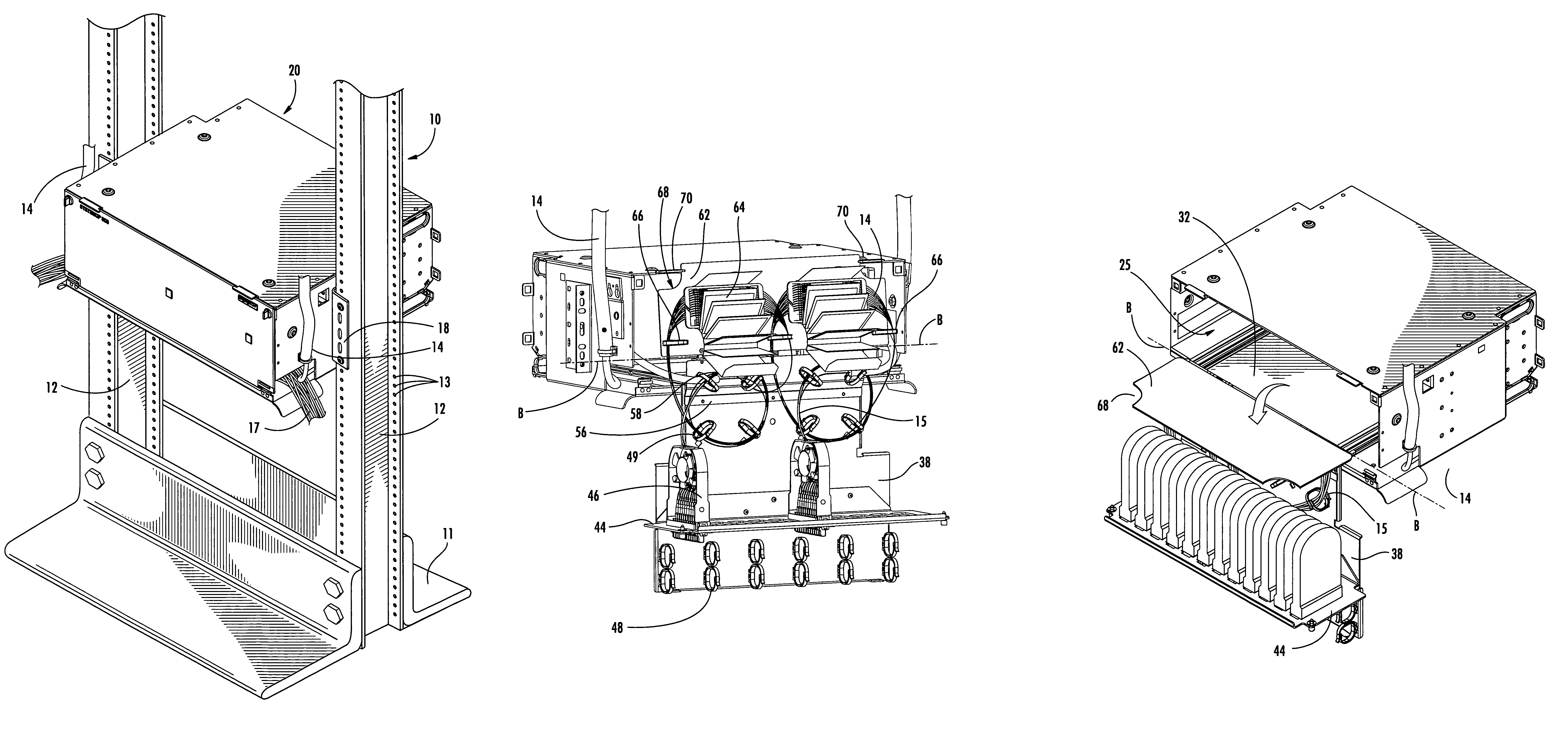
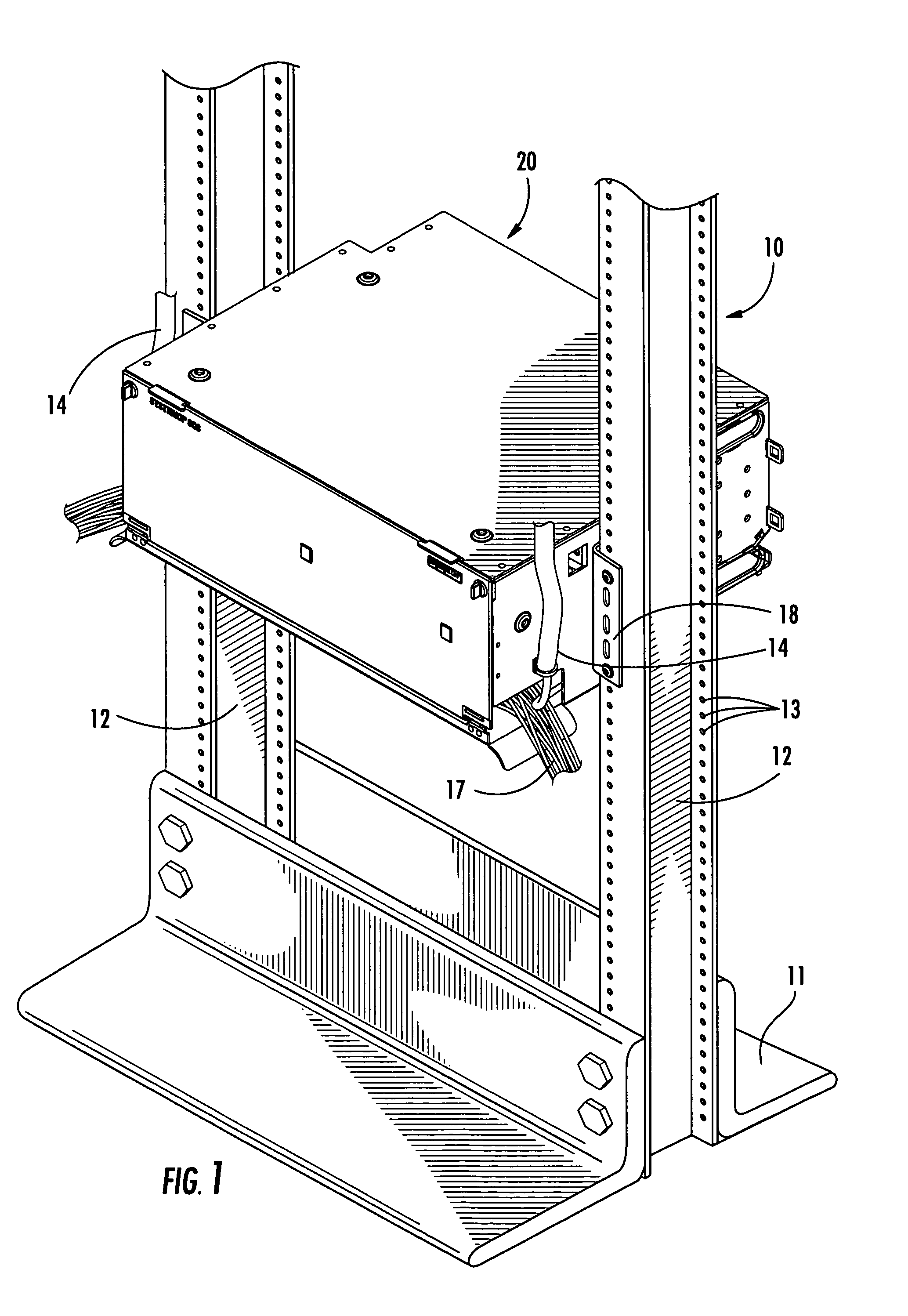
[0023]Turning now to the figures, a typical data center equipment rack, designated broadly at 10, is illustrated in FIG. 1. The rack 10 includes a base 11 that rests on an underlying surface and two uprights 12 that extend vertically from either end of the base 11. The uprights 12 have apertures 13 that enable structures, such as an enclosed shelf 20, to be mounted thereon via mounting...


PUM


Abstract

A shelf includes: a main panel unit; a slide member; and a component mounting panel. The slide member is pivotally attached to the main panel unit for pivotal movement about a first pivot axis and is configured for slidable mounting relative to an enclosure such that the main panel unit can be moved from a retracted position within the enclosure to an extended position that is forward of the enclosure. The main panel unit is pivotable relative to the slide member between a raised position and a lowered position when extended forwardly of the enclosure. The component mounting panel is pivotally mounted to the main panel unit for pivotal movement about a second pivot axis between front access and rear access positions.

Description

FIELD OF THE INVENTION[0001]This invention is directed generally to shelves, and more particularly to multi-functional shelves.BACKGROUND OF THE INVENTION[0002]Data centers that support one or more businesses, factories or residential areas typically comprise one or more racks or cabinets filled with interconnection sites for optical fibers and fiber optic cables. In a typical installation, fiber optic cables that include multiple optical fibers from an external source (these are often known as “outside plant” or “OSP” fibers) enter the cabinet and are spliced together with individual optical fibers known as “pigtails.” Splicing typically occurs in a splice tray or similar component that includes multiple splice sites. The pigtail fibers are then connected within the cabinet to standard termination sites. The termination sites include termination ports that connect optically with “jumper” optical fibers that exit the rack or cabinet to supply data or other information in optical for...

Claims


Application Information

Patent Timeline
Patent Type & Authority Patents(United States)
IPC IPC(8): G02B6/00G02B6/44
CPCG02B6/4455G02B6/4452
Inventor COWLEY, SIMON C.WOMACK, WADE J.
Owner COMMSCOPE INC
Why Eureka
Try Eureka