Compact cellular phone

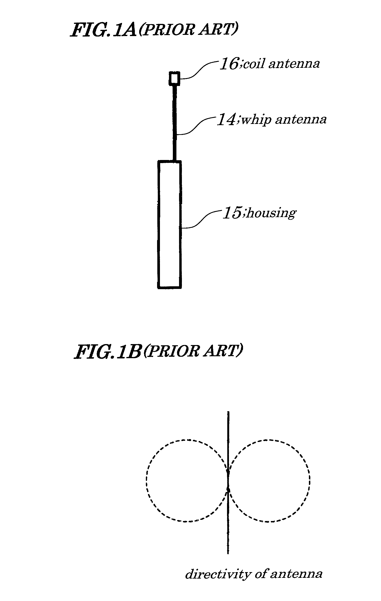
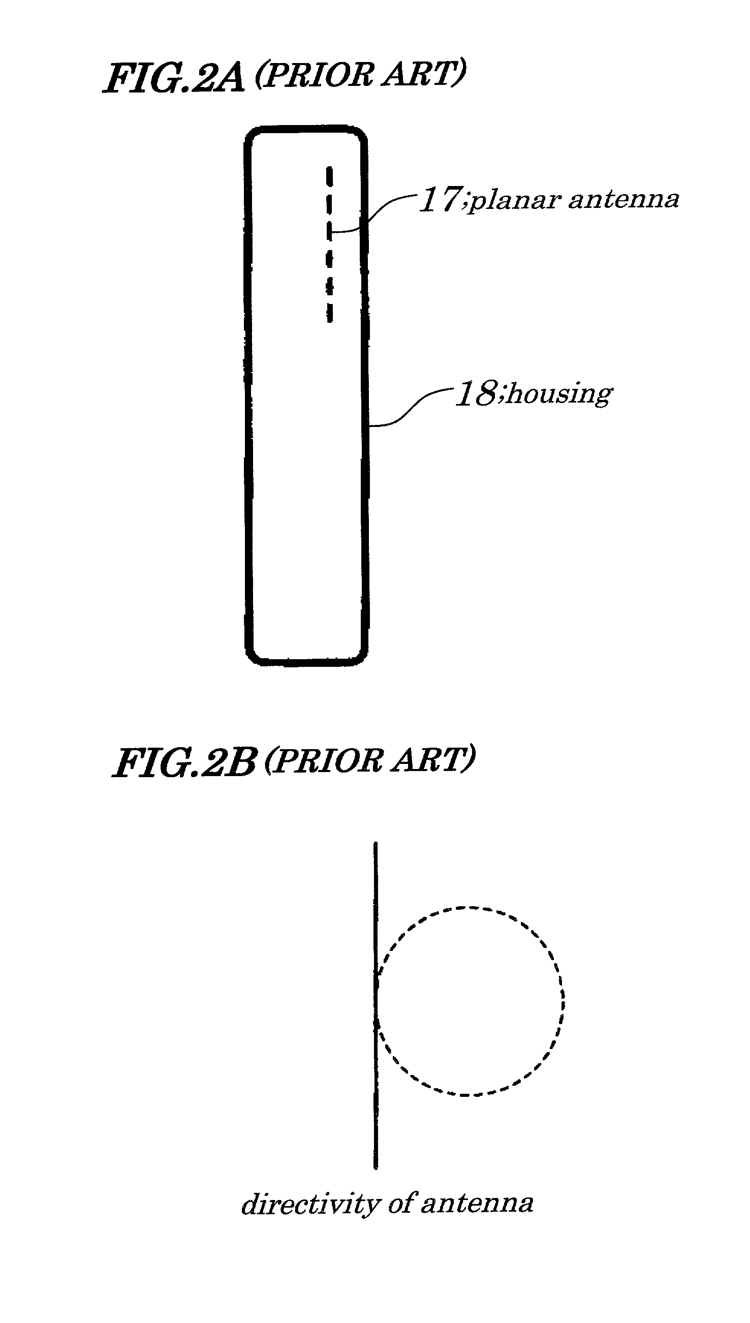
a cellular phone and compact technology, applied in the field of compact cellular phones, can solve the problems of deteriorating transmission efficiency, remarkably degrading transmission quality, and radio wave transmission toward a human being, and achieve the effect of removing influence and favored transmission characteristics

Inactive Publication Date: 2006-04-18
COLTERA
View PDF26 Cites 40 Cited by
  • Summary
  • Abstract
  • Description
  • Claims
  • Application Information

AI Technical Summary

Benefits of technology

[0012]A more specific object of the present invention is to provide the compact cellular phone which is difficult to be influenced by a human head and hand, and which always maintains a preferred transmission quality in both of a waiting state and a transmitting state.
[0021]Furthermore, it possible to eliminate the influence by the human hand holding the compact cellular phone by using at least one of the planar antennas 13A and 13B. Therefore, the preferred transmission characteristics can be maintained.

Problems solved by technology

Thus, the radio wave is transmitted toward a human body and a transmission efficiency is deteriorated by the blocking of the radio wave by the human head.
As a result, the transmission quality is remarkably degraded.
However, since another device for the outer antenna is mounted outside the cellular phone, it is cumbersome to handle the entire cellular phone and a device shape becomes large-sized.

Method used


Image

  • Compact cellular phone
  • Compact cellular phone
  • Compact cellular phone

Examples


embodiment

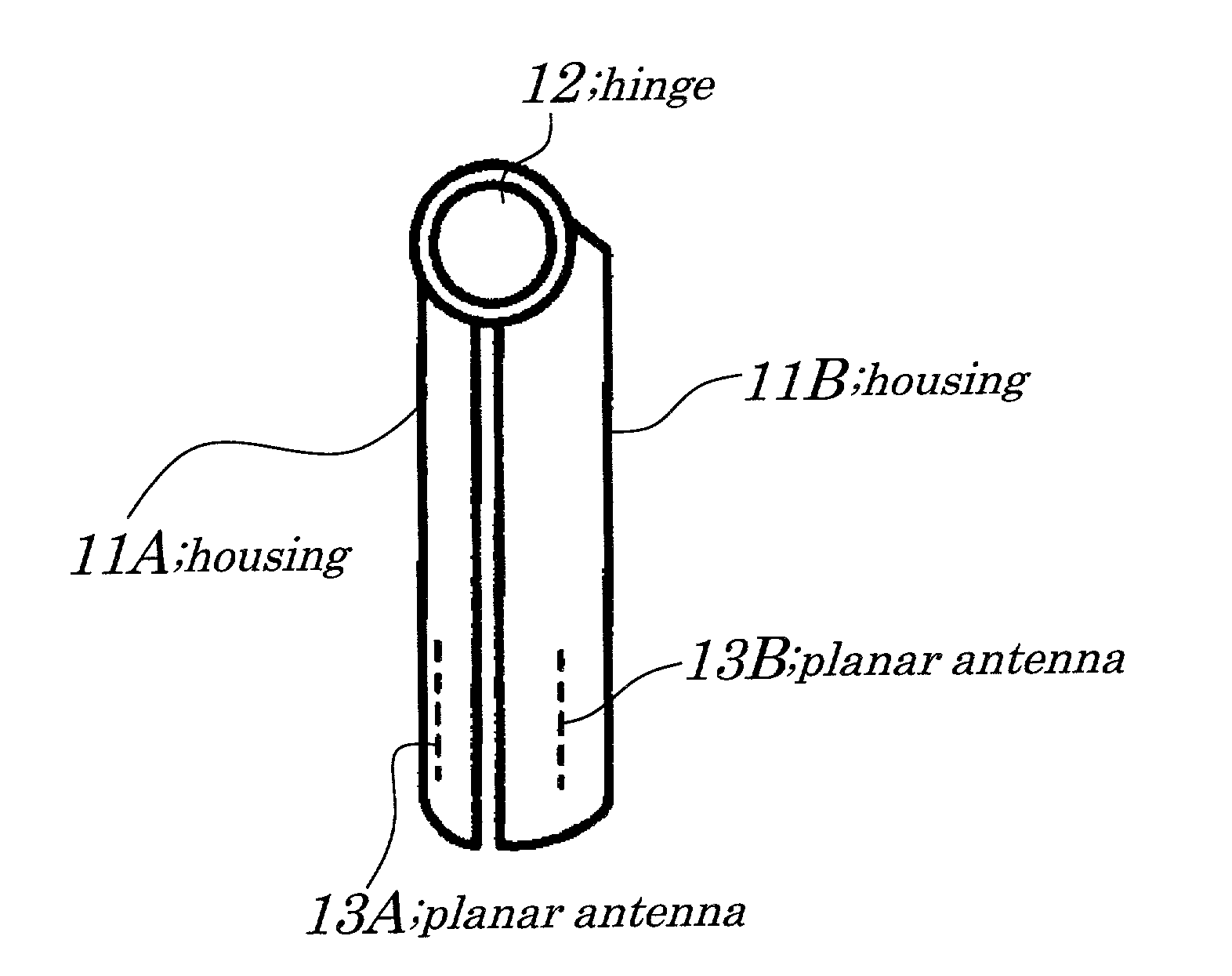
[0031]A compact cellular phone has a foldable configuration and two planar antennas having outward directivities are provided inside two housings in the foldable configuration, respectively. In addition, in awaiting state in which the compact cellular phone is closed and used, both of the two planar antennas or at least one of the two planar antennas is used to transmit. In a communication state in which the compact cellular phone is opened and used, one planar antenna having the better transmission condition between the two planar antennas is selected and used. A space provided between the two planar antennas provided to the compact cellular phone is at least equal to or greater than a palm width (of a human hand) in an open state in which the compact cellular phone is open.

[0032]Also, a planar inverse F-type antenna or a patch antenna can be used as the planar antenna. For each of the two planar antennas, an impedance change is detected and also an physical quantity of a reflectiv...

example

[0035]The example of the present invention will now be described with figures. FIGS. 3A and 3B and FIGS. 4A and 4B show schematic outside views of a compact cellular phone according to the example of the present invention. FIG. 3A is a side elevational view of the compact cellular phone in a closed state, according to the example of the present invention and FIG. 3B is a rear elevational view of the compact cellular phone in the closed state, according to the example of the present invention. FIG. 4A is a side elevational view of the compact cellular phone in an open state, according to the example of the present invention and FIG. 4B is a rear elevational view of the compact cellular phone in the open state, according to the example of the present invention. It should be noted that detailed parts that are not directly related to the present invention are not shown in figures and an explanation thereof is omitted.

[0036]A configuration of the compact cellular phone according to the e...


PUM


Abstract

A compact cellular phone with a foldable configuration and two planar antennas having outward directivities are provided inside the compact cellular phone in the foldable configuration. An interval between the two planar antennas provided to a pair of housings is equal to or wider than a width of a human palm in a state in which the compact cellular phone is open. The two planar antennas are planar inverse F-type antennas or patch antennas and impedance around each of the two planar antennas is measured. Then, one of the two planar antennas, which has a preferred transmission characteristic, is selected and used.

Description

BACKGROUND OF THE INVENTION[0001]1. Field of the Invention[0002]The present invention generally relates to a compact cellular phone, and more particularly to the compact cellular phone in which a pair of housings formed in an approximate flat shape is foldably connected by using a hinge.[0003]The present application claims priority of Japanese Patent Application No. 2000-366700 filed on Dec. 1, 2000, which is hereby incorporated by reference.[0004]2. Description of the Related Art[0005]As shown in FIG. 1A, in a configuration of a conventional cellular phone, a whip antenna 14 has a ¼ wave length or ½ wave length and is provided to a housing 15. And the whip antenna 14 can be retracted into the housing 15. A coil antenna 16 is wound around dielectrics provided at a top end of the whip antenna 14. When the whip antenna 14 is retracted into the housing 15, the coil antenna 16 remains outside the housing 15 and serves as an antenna for a transmission instead of the whip antenna 14. In a...

Claims


Application Information

Patent Timeline
Patent Type & Authority Patents(United States)
IPC IPC(8): H04M1/00H01Q3/24H01Q1/08H01Q1/24H01Q9/04H01Q13/08H04B1/38H04B7/06H04B7/08H04M1/02
CPCH01Q1/243H01Q1/245H04B7/0805H01Q21/28H04B7/0608H01Q9/0421
Inventor KURIYAMA, TOSHIHIDEHANKUI, EIJI
Owner COLTERA
Why Eureka
Try Eureka