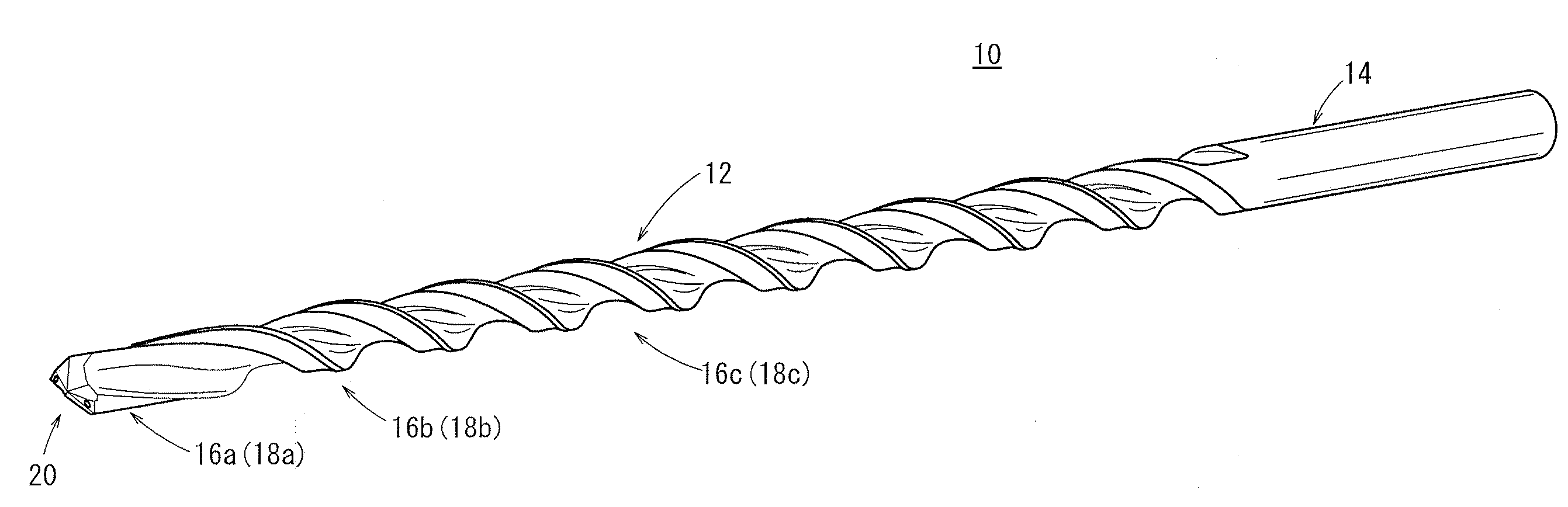
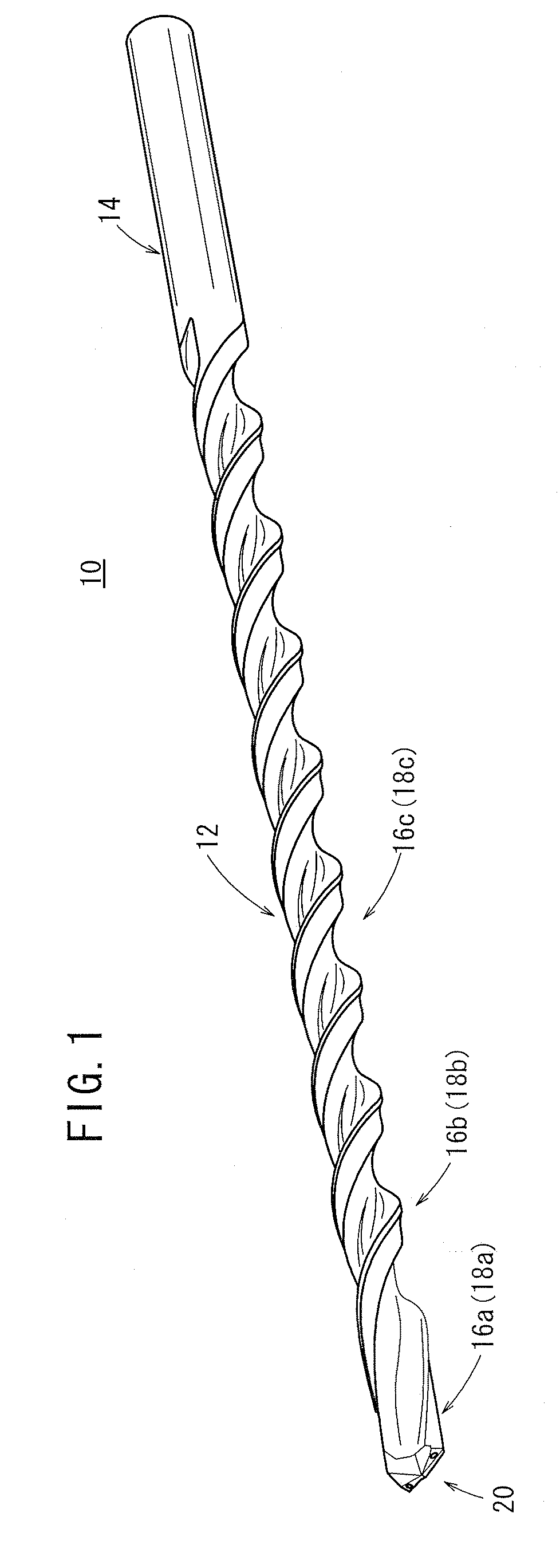
[0010]The present invention has been made in view of the above disadvantages. An object of the present invention is to provide a drill capable of reducing a load applied on the drill when, for instance, a deep hole is bored, thereby prolonging tool lifetime, and enabling swarfs to be smoothly discharged.
[0012]According to the above arrangement, when a deep hole is bored in a workpiece, swarfs can efficiently be discharged from a depth of the deep hole. Thus, clogging of swarfs in the middle of the bored hole can effectively be prevented, and loads on the drill can be reduced, so that the tool lifetime can be prolonged. Further, since the
swarf-discharging speed is improved at the rear-side groove, which is longer than the distal-side cutting blade, an increase in resistance due to
swarf clogging can be prevented.
[0013]In the above aspect of the invention, it is preferable for
a diamond to be provided on the tip end of the blade portion, since dischargeability of swarfs is further improved thereby, and abrasion resistance of the blade tip also is enhanced.
[0014]When the drill is provided with an oil passage, which axially penetrates the drill from the tip end to the rear end thereof, the oil passage constituting a single channel from the shank portion to a section provided with the intermediate groove, and which branches into two channels at the section provided with the intermediate groove, thereby opening at a tip surface of the blade portion at two positions, since only a single channel for the oil passage passes through the axial center of the drill, flow path resistance of the
cutting oil within the oil passage can be lowered.
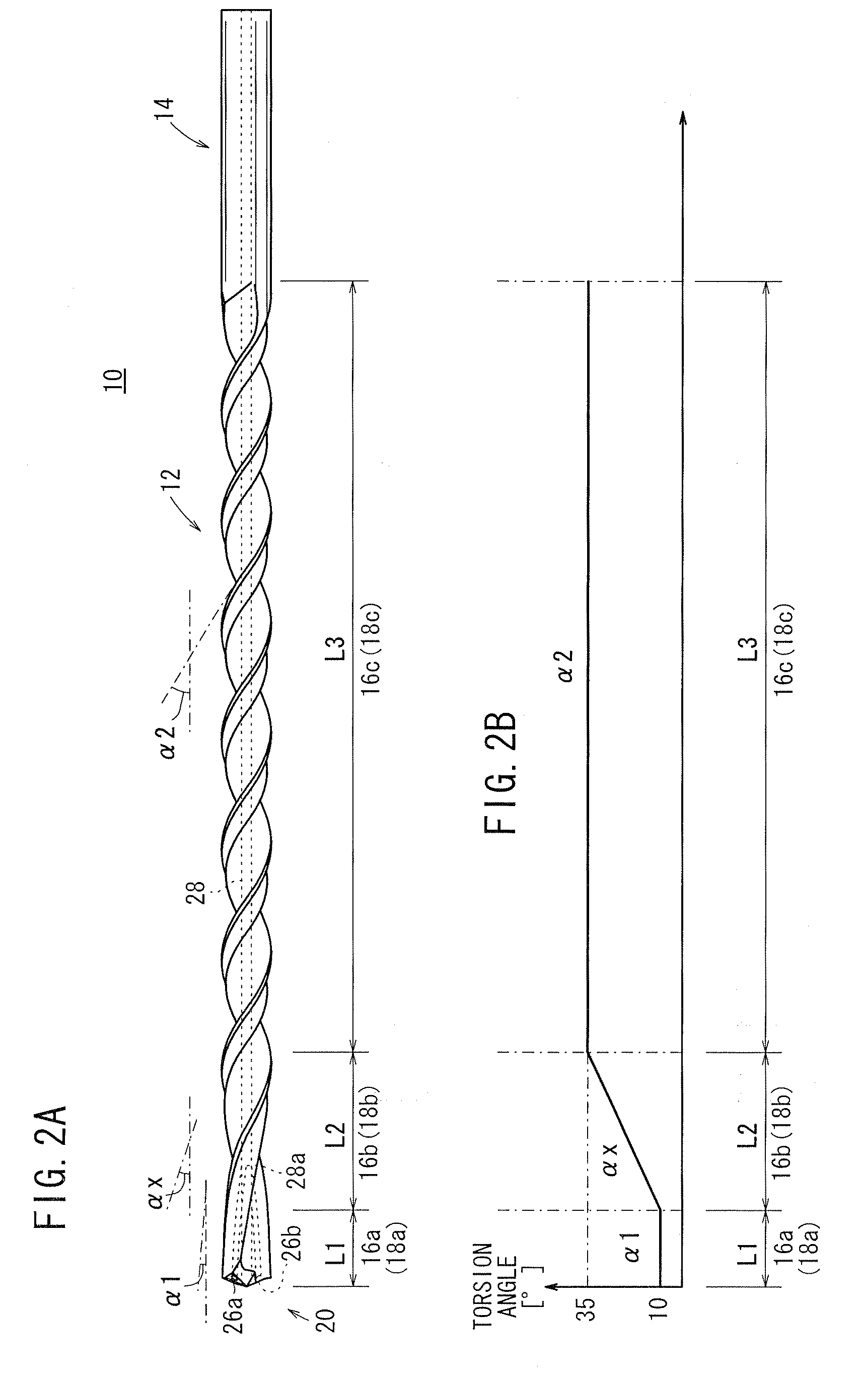
[0015]Further, when the length and torsion angle of the rear-side groove are set larger than the length and torsion angle of the distal-side cutting blade of the blade portion, the size of swarfs generated by the distal-side cutting blade can be reduced, and such swarfs can be discharged efficiently at the rear-side groove. Accordingly, when a deep hole is bored into a workpiece, since swarfs can be discharged efficiently from a depth of the deep hole,
swarf clogging in the middle of the hole as the hole is being bored can effectively be prevented, and the load applied to the drill can be reduced, so that the tool lifetime can be prolonged.
[0016]On the other hand, when the torsion angle of the distal-side cutting blade is set greater than that of the rear-side groove, the drill can
cut into the workpiece while exhibiting a low cutting resistance. Accordingly, when a cast hole formed on a workpiece is drilled, even if the axial direction of the drill becomes misaligned with the axial direction of the cast hole, the drill can enter straightly along the axial direction of the drill, and the drill is hardly influenced by the orientation of the cast hole. Accordingly, even when the
casting accuracy of the cast hole is low, drilling can be conducted securely at a desired position, thereby obtaining high
processing accuracy. Further, since oblique entering of the drill into the cast hole on account of such misalignment, which tends to cause bending and damage to the drill, can be effectively avoided, the tool lifetime can be prolonged.

