
Coating process and apparatus

a technology of coating process and equipment, applied in lighting and heating equipment, drying machines with progressive movements, furnaces, etc., can solve the problems of large volume of filtered air or specialty gases, high cost of auxiliary equipment, and inability to selectively draw primarily the desired gas phase components of air handling systems, etc., to reduce materially the particle count.

Inactive Publication Date: 2006-04-25
3M INNOVATIVE PROPERTIES CO
View PDF53 Cites 51 Cited by
  • Summary
  • Abstract
  • Description
  • Claims
  • Application Information

AI Technical Summary

Benefits of technology

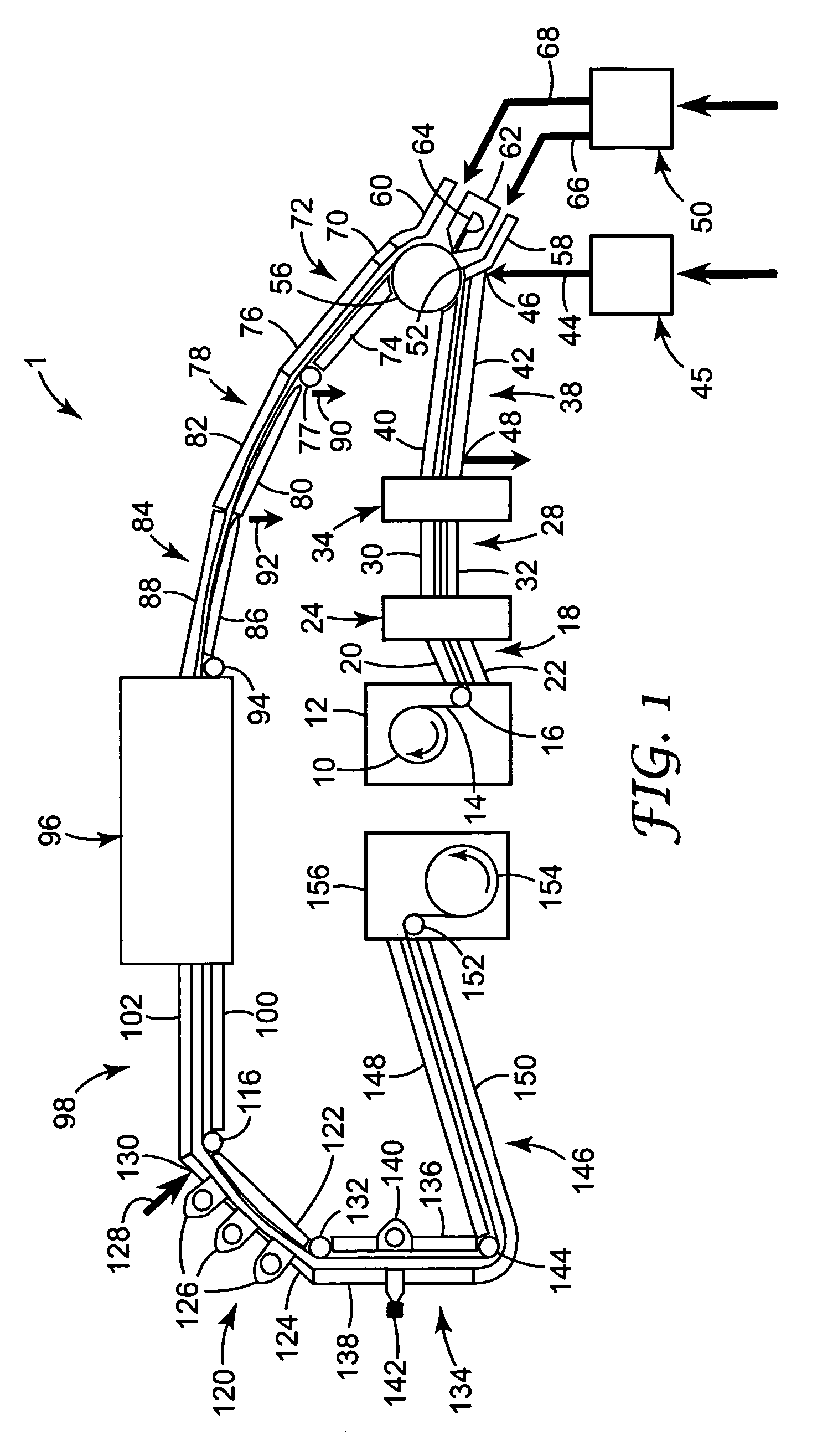
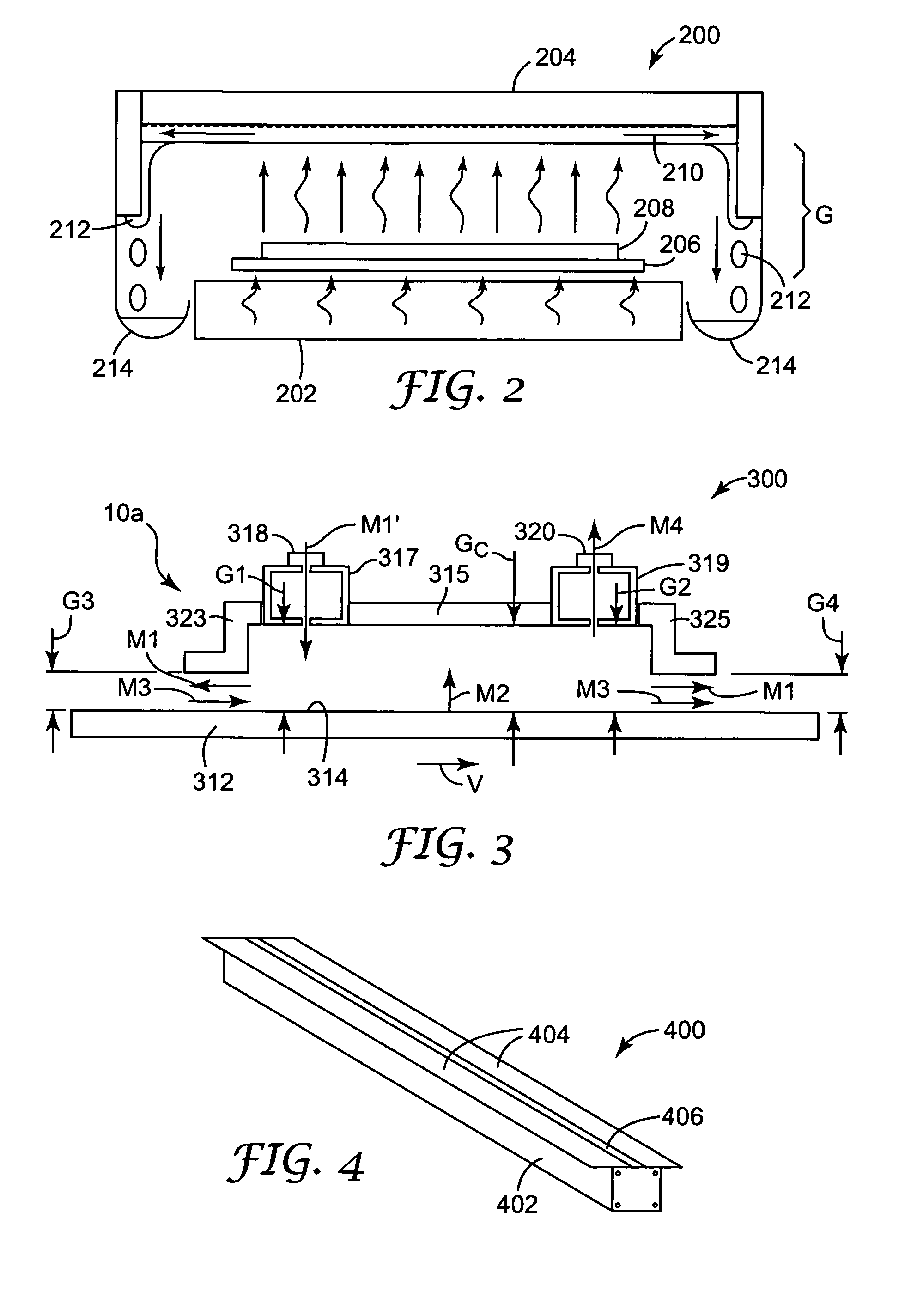
The invention is a process and apparatus for coating a moving substrate in a controlled environment using low volumes of filtered air or specialty gases. The substrate is enveloped from a coating applicator to a dryer or curing station in a close-coupled enclosure or series of interconnected close-coupled enclosures, with one or more streams of conditioned gas flowing at a rate sufficient to reduce particle counts in the close-coupled enclosure. The invention can provide a process for coating a moving substrate of indefinite length, as well as an apparatus for the same. The close-coupled enclosure can also be supplied with conditioned gas to cause a material change in the atmosphere, such as a temperature or humidity change. This can help to improve the quality and efficiency of the coating process.

Problems solved by technology

Clean rooms and special atmospheres require costly auxiliary equipment and large volumes of filtered air or specialty gases.
For example, a typical clean room operation may require many thousands of liters per minute of filtered air.
Conventional open vapor collection systems generally utilize air handling systems that are incapable of selectively drawing primarily the desired gas phase components without drawing significant flow from the ambient atmosphere.
Thus the subsequent separation of vapors from the diluted vapor stream can be difficult and inefficient.
Additionally, the thermodynamics associated with the conventional vapor collection systems often permit undesirable condensation of the vapor at or near the web or coating.
The condensate can then fall onto the web or coating and adversely affect either the appearance or functional aspects of the finished product.

Method used


Image

  • Coating process and apparatus
  • Coating process and apparatus
  • Coating process and apparatus

Examples


example 1

[0096]A single close-coupled enclosure was constructed to illustrate the effect of certain variables. FIG. 9 shows a schematic side sectional view of a close-coupled enclosure 900. Close-coupled enclosure 900 has overlying control surface 902, underlying control surface 904 and side 906 equipped with sample ports A, B and C for measuring pressure, particle count and oxygen levels within close-coupled enclosure 900. Overlying control surface 902 and underlying control surface 904 are spaced apart a distance he1. Underlying control surface 904 is spaced apart from substrate 14 a distance he2. Upstream transition zone 908 has underlying and overlying web slot pieces 910 and 912. These web slot pieces are spaced apart a distance h1a, and have length l1. Underlying web slot piece 910 is spaced apart from web 14 a distance h1b. Downstream transition zone 914 has underlying and overlying web slot pieces 916 and 918. These web slot pieces are spaced apart a distance h2a, and have length l2....

example 2

[0103]Example 1 was repeated using an 18 m / minute web velocity V. The particle count results are shown in FIG. 13 (which uses a logarithmic particle count scale). FIG. 13 demonstrates that for a moving web, material particle count reductions were obtained, at, e.g., pressures greater than −0.5 Pa.

example 3

[0104]Using the method of Example 1, a −0.5 Pa enclosure pressure was obtained in close-coupled enclosure 900 by adjusting the flow rates M1′U and M1′L to 24 liters / min and by adjusting the rate of gas withdrawal at outlet 932 to 94 liters / min. In a separate run, a +0.5 Pa enclosure pressure was obtained by adjusting the flow rates M1′U and M1′L to 122 liters / min and by adjusting the rate of gas withdrawal at outlet 932 to 94 liters / min. The respective particle counts were 107,889 at −0.5 Pa, and only 1 at +0.5 Pa. For each run the enclosure pressure above the substrate was measured at several points along the length of close-coupled enclosure 900 using holes 2, 5, 8, 11 and 14 (see FIG. 10). As shown in FIG. 14, the enclosure pressure above the substrate was very steady for each run and did not measurably vary along the length of close-coupled enclosure 900. Similar measurements were made below the web using ports A, B and C. No variation in pressure was observed in those measureme...


PUM

PropertyMeasurementUnit
pressureaaaaaaaaaa
volumeaaaaaaaaaa
heightaaaaaaaaaa

Abstract

A web coating process and apparatus employing a coating applicator, dryer or curing station and web-handling equipment for conveying the web past the coating applicator and through the dryer. The web is enclosed from at least the coating applicator to the dryer or curing station in a close-coupled enclosure or series of close-coupled enclosures supplied with one or more streams of conditioned gas flowing at a rate sufficient to reduce materially the particle count or change materially a physical property of interest in a close-coupled enclosure.

Description

CROSS-REFERENCE TO RELATED APPLICATIONS[0001]This application is a continuation-in-part of and claims priority to U.S. patent application Ser. No. 10 / 421,195, filed Apr. 23, 2003, which in turn is a continuation-in-part of and claims priority to U.S. patent application Ser. No. 09 / 960,131, filed Sep. 21, 2001 (now U.S. Pat. No. 6,553,689 B2), which in turn claims priority to U.S. Provisional Application Ser. No. 60 / 235,214, filed Sep. 24, 2000, 60 / 235,221, filed Sep. 24, 2000, and 60 / 274,050, filed Mar. 7, 2001, all of which are hereby incorporated by reference in their entirety.FIELD OF THE INVENTION[0002]This invention relates to coating processes and equipment for treating moving substrates of indefinite length.BACKGROUND[0003]Moving substrates of indefinite length (viz., moving webs) can be coated in controlled environments when ordinary ambient air conditions might disrupt the coating process or pose a safety hazard. Typical controlled environments include clean rooms and the u...

Claims


Application Information

Patent Timeline
Patent Type & Authority Patents(United States)
IPC IPC(8): F26B13/00B05C3/12B05C5/02B05C9/06B05C9/10B05C9/12B05C9/14B05C11/115B05C15/00B05D3/04F26B3/00F26B3/34F26B13/10F26B25/00G03C1/74G11B5/842
CPCB05C9/10B05C9/12B05C9/14B05C11/115B05D3/0486F26B13/005F26B13/10F26B25/006B05C15/00B05C5/0254B05C9/06G11B5/842G03C1/74B05C3/12
Inventor KOLB, WILLIAM BLAKEHUELSMAN, GARY L.
Owner 3M INNOVATIVE PROPERTIES CO
Learn More