Support structure carrying thrust load of transmission, method of manufacturing thereof and thrust needle roller bearing

a technology of transmission and support structure, which is applied in the direction of fluid gearing, mechanical equipment, and gearing, etc., can solve the problems of greater differential slip (skew of the roller), breakage of the oil film, and inferior lubricating ability of additive-containing oil to normal oil, so as to improve the inflow and outflow of lubricating oil, improve the strength durability, and reduce the differential slip of the needle roller

Active Publication Date: 2006-04-25
NTN CORP
View PDF19 Cites 19 Cited by
  • Summary
  • Abstract
  • Description
  • Claims
  • Application Information

AI Technical Summary

Benefits of technology

[0013]The present invention has been made in view of the above-discussed circumstances and an object of the present invention is to provide a support structure which carries a thrust load of a transmission, a method of manufacturing thereof and a thrust needle roller bearing, with an improvement of the inflow and outflow of a lubricating oil, a reduction of the differential slip of needle rollers, and an improvement of the strength durability.

Problems solved by technology

The additive-containing oil is inferior to normal oils in lubricating ability for bearings.
This difference is greater as the roller is longer with respect to the outer diameter of the roller, resulting in a greater differential slip (skew of the roller).
The occurrence of the differential slip causes breakage of an oil film and consequently metal-to-metal contact.
Then, the metal-to-metal contact portion generates heat and thereby surface damage (smearing) as well as surface-originated peeling are likely to occur, particularly when the rotational speed is higher.
If the amount of the oil is scarce, metal-to-metal contact between the needle rollers and the race occurs, possibly resulting in surface damage at an earlier stage.

Method used


Image

  • Support structure carrying thrust load of transmission, method of manufacturing thereof and thrust needle roller bearing
  • Support structure carrying thrust load of transmission, method of manufacturing thereof and thrust needle roller bearing
  • Support structure carrying thrust load of transmission, method of manufacturing thereof and thrust needle roller bearing

Examples


first embodiment

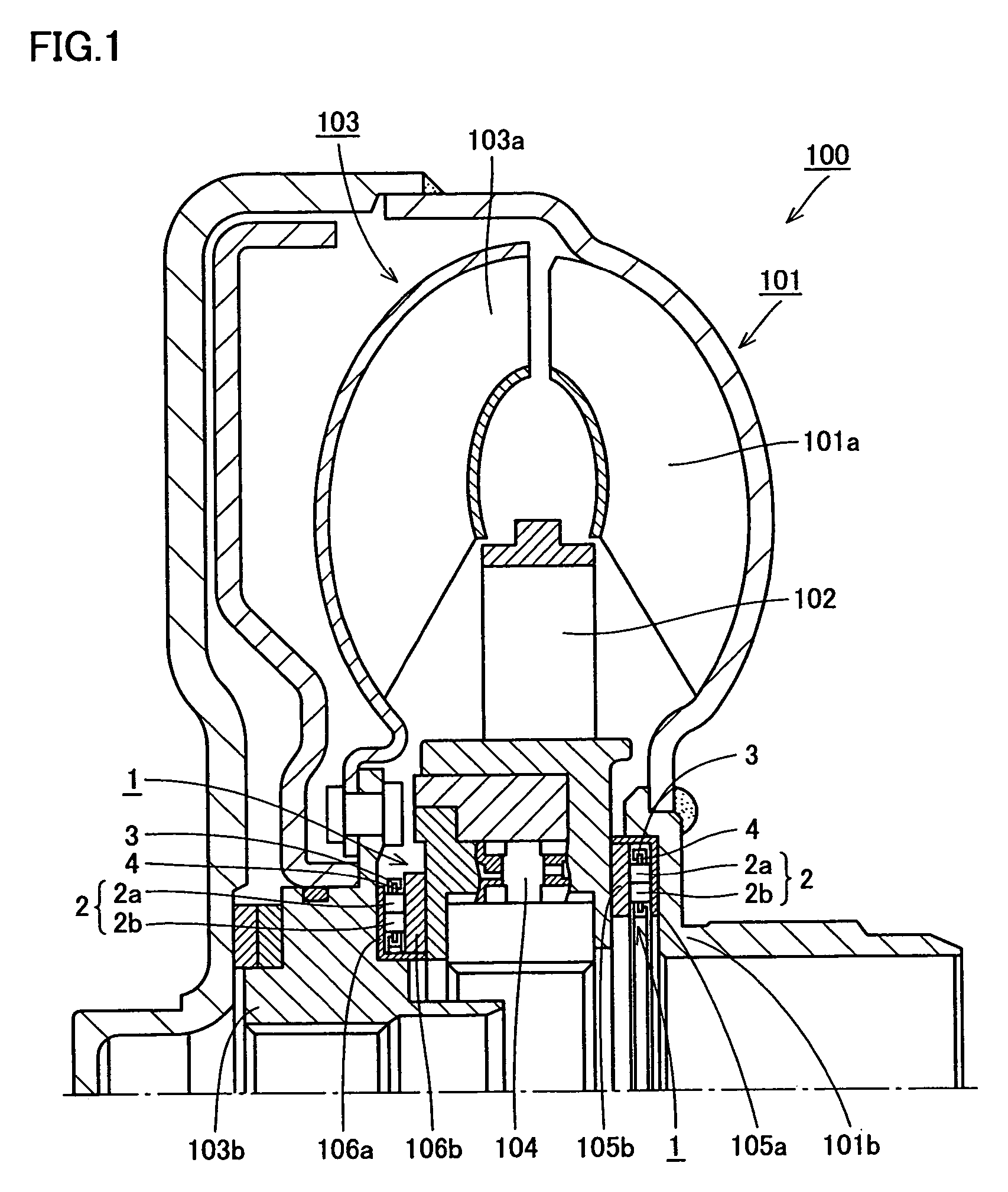
[0074]Referring to FIG. 1, a transmission, for example, an automatic transmission is shown. The automatic transmission is usually constituted of a torque converter 100 and a planetary gear mechanism (not shown).

[0075]Torque converter 100 chiefly includes an impeller 101, a stator 102 and a turbine 103. According to this embodiment, a support structure carrying a thrust load of the transmission corresponds to thrust needle roller bearings 1 attached, for example, between impeller 101 and stator 102 and between stator 102 and turbine 103.

[0076]In this torque converter 100, impeller 101 coupled to an output shaft of an engine and turbine 103 coupled to an input shaft of the transmission are arranged opposite to each other. Stator 102 is attached, via a one-way clutch 104, to a stator shaft fixed to a casing. This stator 102 serves to redirect a fluid circulating between impeller blades 101a and turbine blades 103a that are cup-shaped, when the fluid returns from turbine 103 to impeller...

second embodiment

[0102]This embodiment has its structure different from that of the first embodiment only in the shape of cages and caulking method. It is noted that the same or similar components or parts to those of the first embodiment are denoted by like reference characters and description thereof is not repeated here.

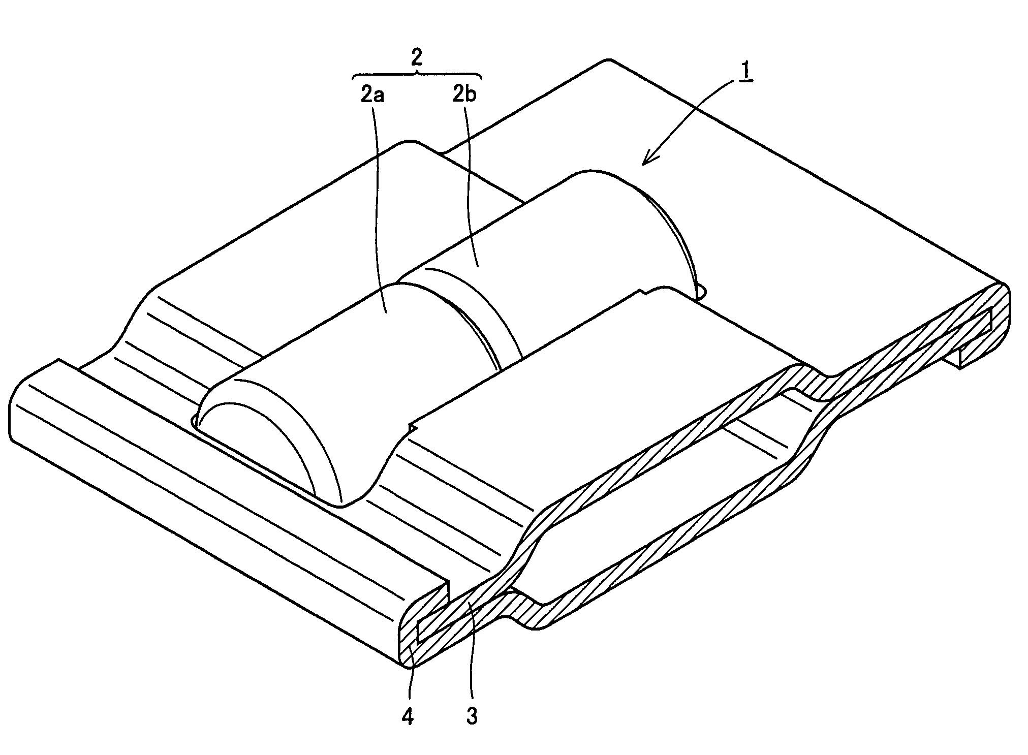
[0103]Referring to FIGS. 7A–7E, thrust needle roller bearing 11 applied to a support structure which carries a thrust load of the transmission has a plurality of needle rollers 2 and two annular cages 13 and 14 that hold these needle rollers 2 at predetermined pitches in the circumferential direction. As shown in FIG. 7D, the upper one of two cages 13 and 14, namely upper cage 13, includes a roller holder portion 15a having its radially outer portion which includes a sloping extension 13a formed by bending the outer end of roller holder portion 15a and an outer plate-like portion 13b formed by bending the lower end of sloping extension 13a in the radial direction.

[0104]Roller hold...

third embodiment

[0109]This embodiment differs in structure from the second embodiment only in the direction of the caulking. It is noted that the same or similar components or parts to those of the second embodiment are denoted by like reference characters and detailed description thereof is not repeated here.

[0110]Referring to FIGS. 8A–8D, thrust needle roller bearing 11′ applied to a support structure which carries a thrust load of the transmission has a plurality of needle rollers 2 and two annular cages 13′ and 14′ that hold these needle rollers 2 at predetermined pitches in the circumferential direction. Of two cages 13′ and 14′, upper cage 13′ includes a roller holder portion 15a which has its radially outer portion including, as shown in FIG. 8C, a sloping extension 13a formed by bending the outer end of roller holder portion 15a and an outer plate-like portion 13b formed by bending the lower end of sloping extension 13a in the radial direction. Roller holder portion 15a of upper cage 13 als...


PUM

PropertyMeasurementUnit
temperatureaaaaaaaaaa

Abstract

A support structure carries a thrust load of a transmission which includes a torque converter having an impeller and a turbine opposite to each other with a stator therebetween. A thrust needle roller bearing having needle rollers arranged in two rows is provided at, at least one of places respectively between the stator and the impeller and between the stator and the turbine. The support structure carrying a thrust load of the transmission, a method of manufacturing the support structure and the thrust needle roller bearing are thus obtained, with an improvement in inflow and outflow of a lubricating oil, a reduction of the differential slip of the needle rollers, and an improvement in strength durability.

Description

BACKGROUND OF THE INVENTION[0001]1. Field of the Invention[0002]The present invention relates to a support structure carrying a thrust load of a transmission, a method of manufacturing the support structure and a thrust needle roller bearing.[0003]2. Description of the Background Art[0004]A thrust needle roller bearing is constituted of needle rollers, a cage and a race, and is structured to allow the needle rollers to be in line contact with the race. Therefore, despite of a small bearing area, this type of bearing is advantageous because of its high load capacity and high stiffness. The thrust needle roller bearing is thus suitable for use under hostile conditions, for example, during a drive under conditions like scarce lubrication and high-velocity rotation, and is accordingly used as a support structure carrying a thrust load of an automatic transmission of an automobile (e.g. support structure for a continuously variable transmission).[0005]A conventional thrust needle roller ...

Claims


Application Information

Patent Timeline
Patent Type & Authority Patents(United States)
IPC IPC(8): F16C33/48F16C19/30F16C33/54F16H3/091F16H41/24
CPCF16C33/48F16C33/547F16C43/083F16H41/24F16C33/541F16C19/305F16H3/0915Y10T29/49686F16C2361/61Y10T29/49682Y10T29/4968Y10T29/49645F16C2361/63F16C2361/65
Inventor OBAYASHI, KOUSUKEHAYASHI, TETSUYAOISHI, SHINJI
Owner NTN CORP
Why Eureka
Try Eureka