Support structure carrying thrust load of compressor and thrust needle roller bearing

a technology of thrust needle roller bearing and support structure, which is applied in the direction of machines/engines, mechanical equipment, positive displacement liquid engines, etc., can solve the problems of metal-to-metal contact, skew of rollers, and oil film breakage, so as to improve the strength durability, improve the inflow and outflow of lubricating oil, and reduce the differential slip of needle rollers

Inactive Publication Date: 2008-07-15
NTN CORP
View PDF17 Cites 6 Cited by
  • Summary
  • Abstract
  • Description
  • Claims
  • Application Information

AI Technical Summary

Benefits of technology

[0013]The present invention has been made in view of the above-discussed circumstances and an object of the present invention is to provide a support structure which carries a thrust load of a compressor a...

Problems solved by technology

This difference is greater as the roller is longer with respect to the outer diameter of the roller, resulting in a greater differential slip (skew of the roller).
The occurrence of the differential slip causes breakage of an oil film and consequently metal-to-metal contact.
Then, the metal-to-metal contact portion ge...

Method used


Image

  • Support structure carrying thrust load of compressor and thrust needle roller bearing
  • Support structure carrying thrust load of compressor and thrust needle roller bearing
  • Support structure carrying thrust load of compressor and thrust needle roller bearing

Examples


first embodiment

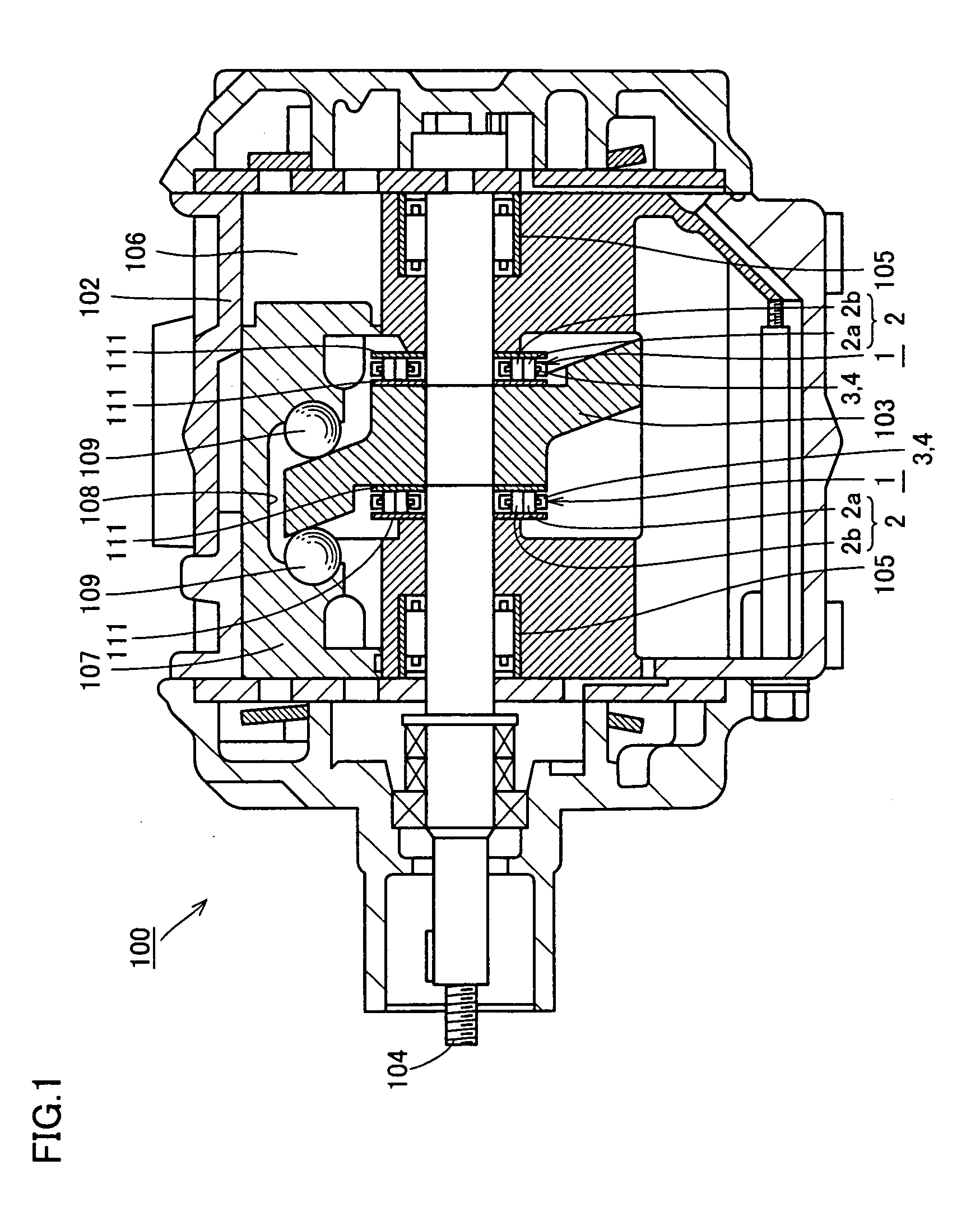
[0070]Referring to FIG. 1, a compressor, for example, a swash-plate compressor 100 of double-swash-plate type is shown. Swash-plate compressor 100 has a swash plate 103 secured to a main shaft 104 and the swash plate rotates to reciprocate a piston 107 via shoes 109 sliding on swash plate 103.

[0071]Main shaft 104 to which swash plate 103 is secured is rotatably supported via a radial bearing 105 in a housing 102. Housing 102 has a plurality of cylinder bores 106 formed therein that are arranged at regular intervals in the circumferential direction, and double-headed piston 107 is sidably held in each bore 106. A depression 108 is formed at a central part of each piston 107 to surround the outer periphery of swash plate 103, and spherical or hemispherical shoes 109 are placed on respective spherical seats that are formed in depression 108 on its surfaces opposite to each other in the axial direction. Shoes 109 placed between swash plate 103 and piston 107 serve to smoothly convert ro...

second embodiment

[0096]A thrust needle roller bearing of this embodiment has its structure different from that of the first embodiment only in the shape of cages and caulking method. It is noted that the same or similar components or parts to those of the first embodiment are denoted by like reference characters and description thereof is not repeated here.

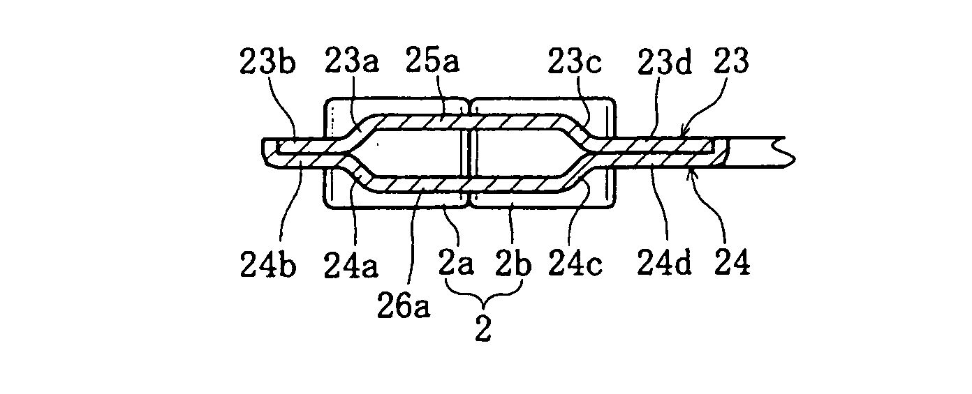
[0097]Referring to FIGS. 7A-7E, thrust needle roller bearing 11 applied to a support structure which carries a thrust load of a compressor has a plurality of needle rollers 2 and two annular cages 13 and 14 that hold these needle rollers 2 at predetermined pitches in the circumferential direction. As shown in FIG. 7D, the upper one of two cages 13 and 14, namely upper cage 13, includes a roller holder portion 15a having its radially outer portion which includes a sloping extension 13a formed by bending the outer end of roller holder portion 15a and an outer plate-like portion 13b formed by bending the lower end of sloping extension 13a in the radi...

third embodiment

[0103]A thrust needle roller bearing of this embodiment differs from that of the above-described second embodiment only in the direction of the caulking. It is noted that the same or similar components or parts to those of the second embodiment are denoted by like reference characters and detailed description thereof is not repeated here.

[0104]Referring to FIGS. 8A-8D, thrust needle roller bearing 11′ applied to a support structure which carries a thrust load of a compressor has a plurality of needle rollers 2 and two annular cages 13′ and 14′ that hold these needle rollers 2 at predetermined pitches in the circumferential direction. Of two cages 13′ and 14′, upper cage 13′ includes a roller holder portion 15a which has its radially outer portion including, as shown in FIG. 8C, a sloping extension 13a formed by bending the outer end of roller holder portion 15a and an outer plate-like portion 13b formed by bending the lower end of sloping extension 13a in the radial direction. Rolle...


PUM


Abstract

A support structure carrying a thrust load of a compressor has a swash plate which contributes to a compressing operation by rotating according to rotation of a rotating shaft which is rotatably supported by a housing. The swash plate is rotatably supported with respect to the housing, and the support structure includes a thrust needle roller bearing having double-row needle rollers. The support structure carrying a thrust load of a compressor and the thrust needle roller bearing are thus obtained, with an improvement in inflow and outflow of a lubricating oil, a reduction of the differential slip of the needle rollers, and an improvement in strength durability.

Description

BACKGROUND OF THE INVENTION[0001]1. Field of the Invention[0002]The present invention relates to a support structure which carries a thrust load of a compressor as well as a thrust needle roller bearing.[0003]2. Description of the Background Art[0004]A thrust needle roller bearing is constituted of needle rollers, a cage and a race, and is structured to allow the needle rollers to be in line contact with the race. Therefore, despite of a small bearing area, this type of bearing is advantageous because of its high load capacity and high stiffness. The thrust needle roller bearing is thus suitable for use under hostile conditions, for example, during a drive under conditions like scarce lubrication and high-velocity rotation, and is accordingly used as a support structure carrying a thrust load of a compressor for an air conditioner of an automobile.[0005]A conventional thrust needle roller bearing is known from Japanese Patent Laying-Open No. 2002-70872 according to which at least on...

Claims


Application Information

Patent Timeline
IPC IPC(8): F01B3/00F16C33/46F04B27/08F04B27/10F04B39/00F16C19/30F16C19/46F16C33/48F16C33/54
CPCF04B27/1063F16C33/48F16C33/547F16C19/305F16C33/541F16C43/083F16C2240/40F16C2202/04F16C2360/42F16C2360/00
Inventor OBAYASHI, KOUSUKEHAYASHI, TETSUYAOISHI, SHINJI
Owner NTN CORP
Why Eureka
Try Eureka