Current sensing circuit and method

a current sensing circuit and current sensing technology, applied in multi-tester circuits, fault locations, instruments, etc., can solve the problems of damage to sensitive devices, latency between detection of over-current conditions and response, and loss of fets in motor driver circuits

Active Publication Date: 2006-04-25
TEXAS INSTR INC
View PDF11 Cites 28 Cited by
  • Summary
  • Abstract
  • Description
  • Claims
  • Application Information

AI Technical Summary

Benefits of technology

[0008]The present invention achieves technical advantages as a circuit and method designed to sense current in a circuit, such as a motor driver control circuit. The present invention achieves certain advantages by integrating the sense FET and current mirrors into a voltage following operational amplifier circuit and mirroring the sensed current off the internal current mirrors.

Problems solved by technology

For example, if a motor is stalled, it might accept large currents that can destroy the FETs in the motor driver circuit, such as an H-bridge.
However, these circuits that have an on-board micro-controller generating a PWM signal to drive a motor have certain drawbacks.
However, there is a latency between detection of the over-current condition and the response.
Disadvantageously, this delay can result in an over-current condition before the PWM ratio is reduced, thus damaging sensitive devices.
These arrangements consume power and require a large area to implement the design.
In these arrangements, the measured current is dependent on the current flowing through the narrower FET as well as the temperature, and thus accurate control is difficult to achieve.

Method used


Image

  • Current sensing circuit and method
  • Current sensing circuit and method

Examples


Embodiment Construction

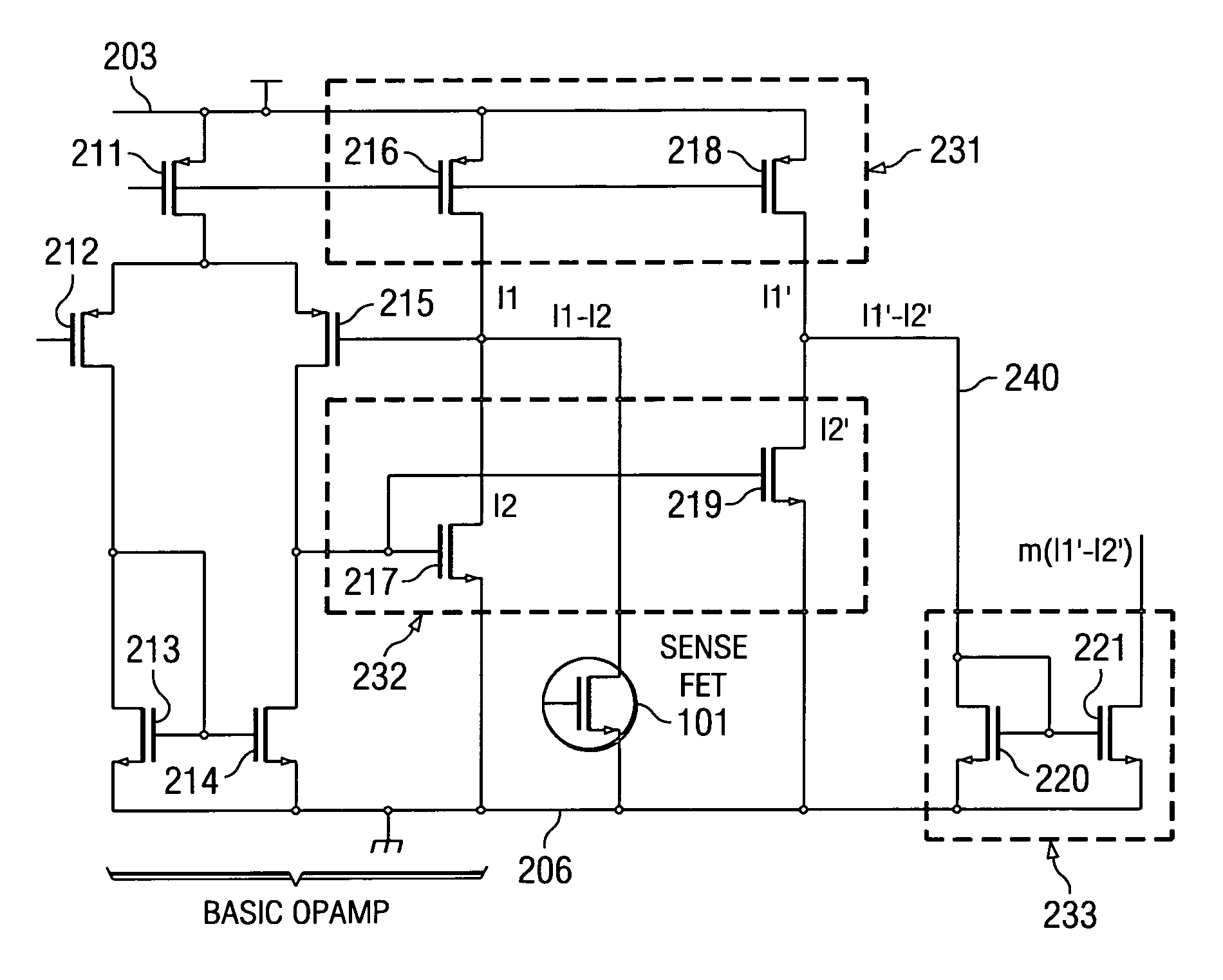
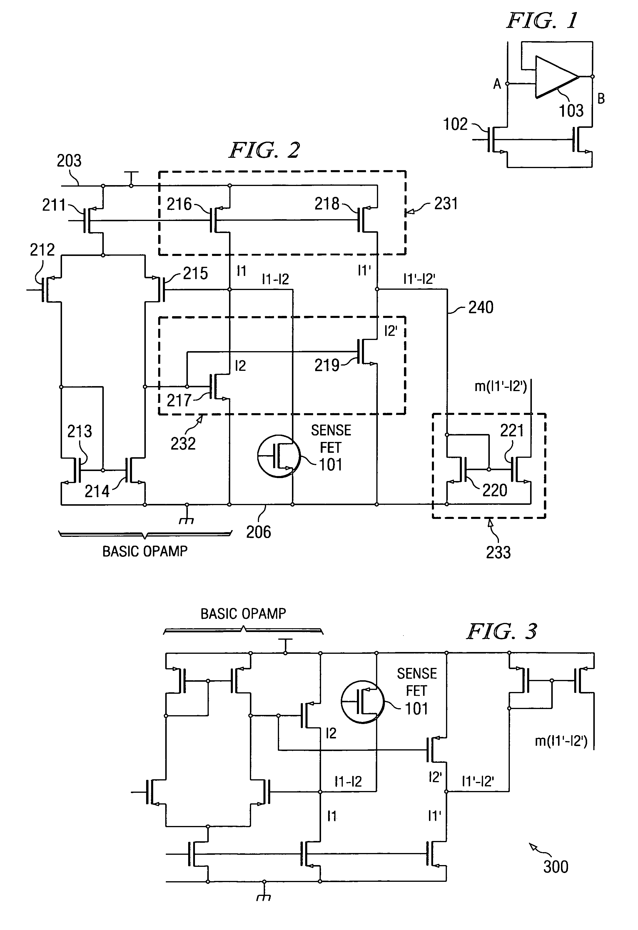
[0013]The numerous innovative teachings of the present invention will be described with particular reference to a motor driver control application. However, it should be understood that the motor driver control circuit is only one example of the many advantageous applications and innovative teachings herein. In general, statements made in the specification of the present motor driver control circuit application do not necessarily delimit any of the various claimed inventions. Moreover, some statements may apply to some inventive features, but not to others. Detailed descriptions of known functions and constructions unnecessarily obscuring the subject matter of the present invention have been omitted for clarity.

[0014]The present invention achieves technical advantages as a current sensing circuit and method due to its improved accuracy of current sensing with at least one sense FET. A plurality of sense FETs may be connected in parallel and / or separated by switches for variable cont...


PUM


Abstract

The present invention includes a plurality of FETs (211, 212, 213, 214, 215, 216, 217) including an operational amplifier with additional FETs (218, 219, 220,221) arranged as current mirrors, and a sense FET (101), and a current sensed at FET (101) is amplified, compared to a reference signal, the difference current derived from the amplified sense current and reference signal being amplified and provided at an output for use in control applications.

Description

FIELD OF THE INVENTION[0001]The present invention generally relates to circuits and methods for current sensing, for use in a variety of applications including motor driver control circuits and servo circuits.BACKGROUND OF THE INVENTION[0002]Motor driver circuits are essentially small current amplifiers or transconductance amplifiers. In a small current amplifier, the input is a control current and the output is a current that can be used to drive a motor. In a transconductance amplifier, the input is a control voltage and the output is a current that can be used to drive a motor. As can be seen, the function of these circuits is to take a low-current or voltage control signal, and turn it into a proportionally higher-current signal. For example, in a motor driver circuit, the control signal may be on the order of microamps or milliamps, and the motor may require amps for operation.[0003]Typical in such motor driver circuits is an ancillary current sensing circuit. Current sensing i...

Claims


Application Information

Patent Timeline
Patent Type & Authority Patents(United States)
IPC IPC(8): G01R15/12G01R33/00H03F3/45
CPCH03F3/45273
Inventor PETERSON, KIRK DAVID
Owner TEXAS INSTR INC
Why Eureka
Try Eureka