Method and system for limiting use of electronic equipment

a technology for limiting the use of electronic equipment and electronic equipment, applied in the field of electronic equipment, can solve the problems of increasing the difficulty of thwarting, the loss of use of electronic equipment by owners, and the inability of employees to take electronic equipment home or elsewhere and use it in unauthorized ways, so as to improve the security of electronic equipment and reduce the effect of inefficiencies

Active Publication Date: 2006-04-25
INTERMEC IP
View PDF9 Cites 21 Cited by
  • Summary
  • Abstract
  • Description
  • Claims
  • Application Information

AI Technical Summary

Benefits of technology

[0011]It is an advantage of the present invention to achieve improved security for electronic equipment while reducing inefficiencies resulting from security measures.
[0012]The present invention is an apparatus and method for securing electronic equipment which is designed to satisfy the aforementioned needs, provide the previously stated objects, include the above-listed features, and achieve the already articulated advantages. The present invention is carried out in a “theft benefit elimination system” in a sense that the ordinary benefit a thief seeks when removing electronic equipment from its proper place has been greatly reduced.

Problems solved by technology

In the past, owners of electronic equipment have encountered losses of use of their electronic equipment when such equipment is misappropriated from its space of intended operation.
Employees of a company may take electronic equipment home or elsewhere and use them in unauthorized ways.
However, if the equipment is being misappropriated by an employee, then it becomes more difficult to thwart.
The problems of securing mobile equipment become even more difficult.
Often, measures to limit misappropriation reduce the ability to fully utilize the equipment.
This creation of inefficiencies of use upon the proper users of the equipment can be burdensome and is undesirable.

Method used


Image

  • Method and system for limiting use of electronic equipment
  • Method and system for limiting use of electronic equipment
  • Method and system for limiting use of electronic equipment

Examples


Embodiment Construction

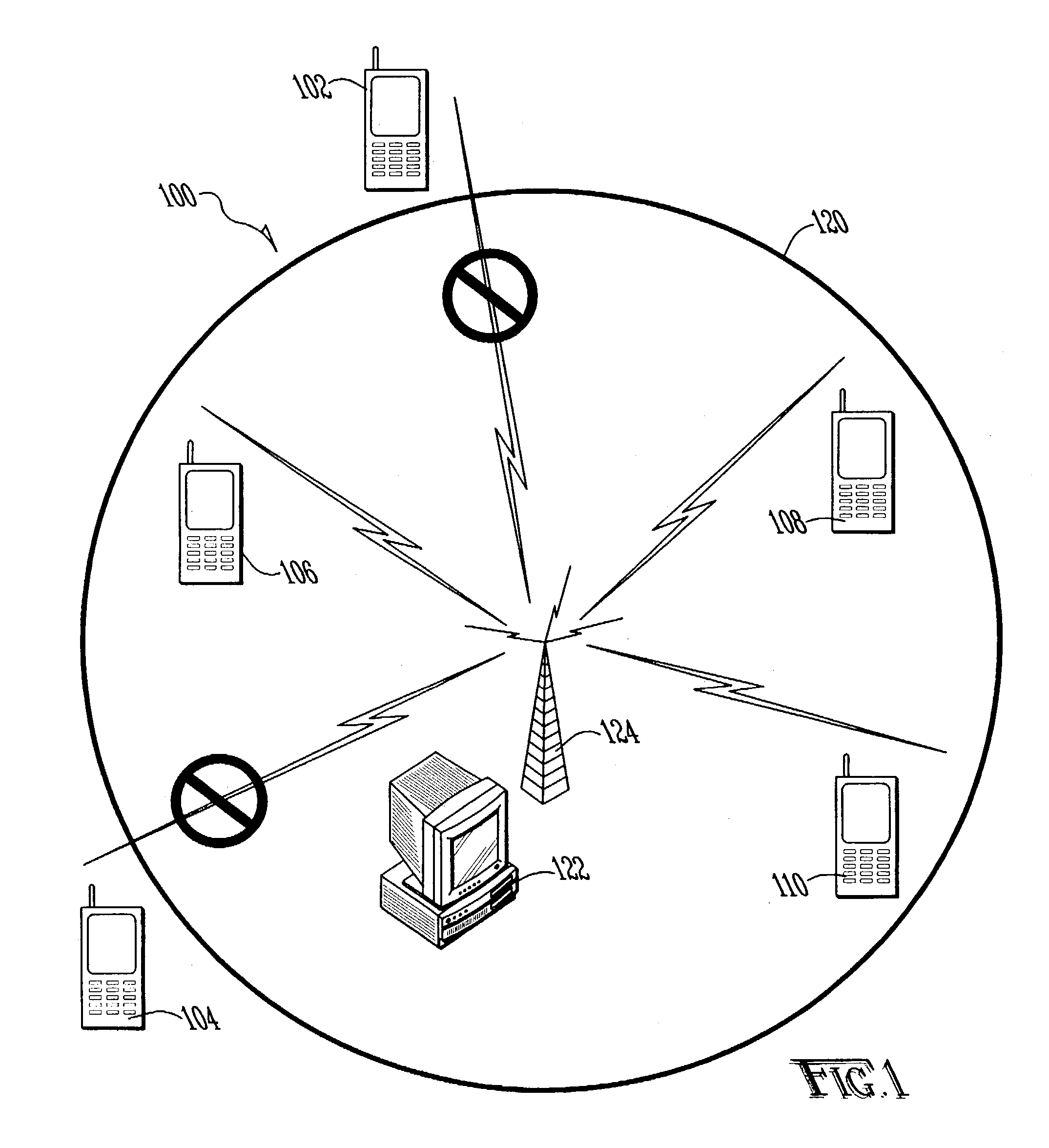
[0017]Now referring to the drawings wherein like numerals refer to like matter throughout, and more specifically referring to FIG. 1, there is shown a system of the present invention generally designated 100, including numerous electronic devices 102, 104,106, 108 and 110. These electronic devices are depicted as handheld wireless terminals. However, the present invention is intended to include any type of electronic device, such as, but not limited to, the following: desktop personal computers, mobile computing devices, laptop computers, bar code scanners and other types of scanners, printers, infrastructure equipment, network access points, routers, radio frequency (RF) or other identification tag decoding machines, network managers and controllers. While the above list of equipment includes only electronic equipment which typically are coupled to and use computer networks, the present invention is intended to include even more electronic devices, such as security, navigation, or ...


PUM


Abstract

A system and method for securing electronic devices with a non-physical tether which automatically disables operation of the device when the device fails to confirm its location within a predetermined area and / or connection to a predetermined network.

Description

[0001]This application claims the benefit of Provisional Application No. 60 / 319,567, filed Sep. 23, 2002.FIELD OF THE INVENTION[0002]The present invention relates to electronic equipment, and more specifically relates to methods and systems for monitoring the location of and limiting the use of protected object, and even more specifically relates to systems and methods which determine a status of a protected object as being within a predetermined space of intended location or operation and limiting uses of such protected object based upon such status and otherwise affecting identification and / or security of such protected object.BACKGROUND OF THE INVENTION[0003]In the past, owners of electronic equipment have encountered losses of use of their electronic equipment when such equipment is misappropriated from its space of intended operation. Theft is an obvious example of such a misappropriation. Other examples exist as well. Employees of a company may take electronic equipment home o...

Claims


Application Information

Patent Timeline
Patent Type & Authority Patents(United States)
IPC IPC(8): H04Q1/00G08B13/14
CPCG08B13/1409
Inventor UNGS, KELLY J.
Owner INTERMEC IP
Why Eureka
Try Eureka