Method of radar pattern recognition by sorting signals into data clusters

Active Publication Date: 2006-04-25
HARRIS CORP
View PDF7 Cites 54 Cited by
  • Summary
  • Abstract
  • Description
  • Claims
  • Application Information

AI Technical Summary

Problems solved by technology

Unless these signals are sorted and separated from each other, it is not possible for the aircraft to determine the types of classes of radars it is abou

Method used


Image

  • Method of radar pattern recognition by sorting signals into data clusters
  • Method of radar pattern recognition by sorting signals into data clusters
  • Method of radar pattern recognition by sorting signals into data clusters

Examples


Embodiment Construction

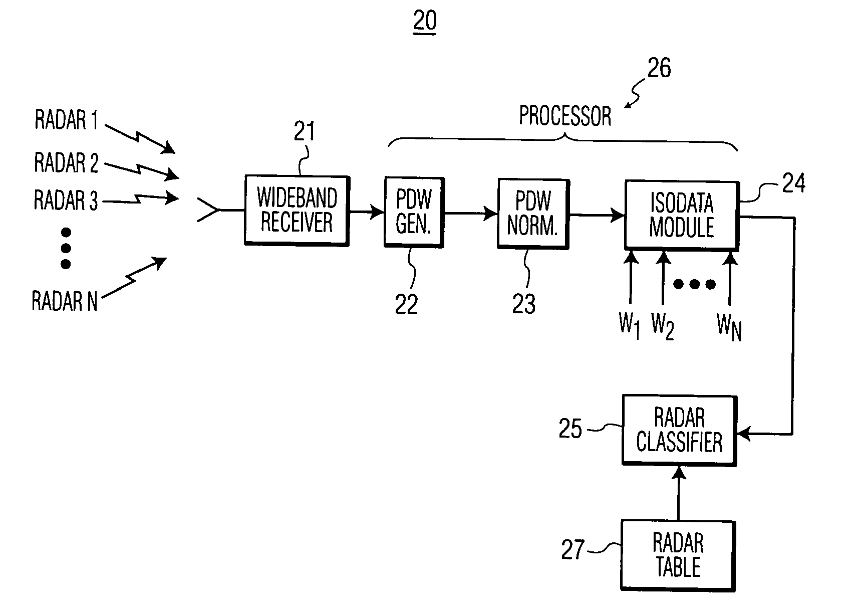
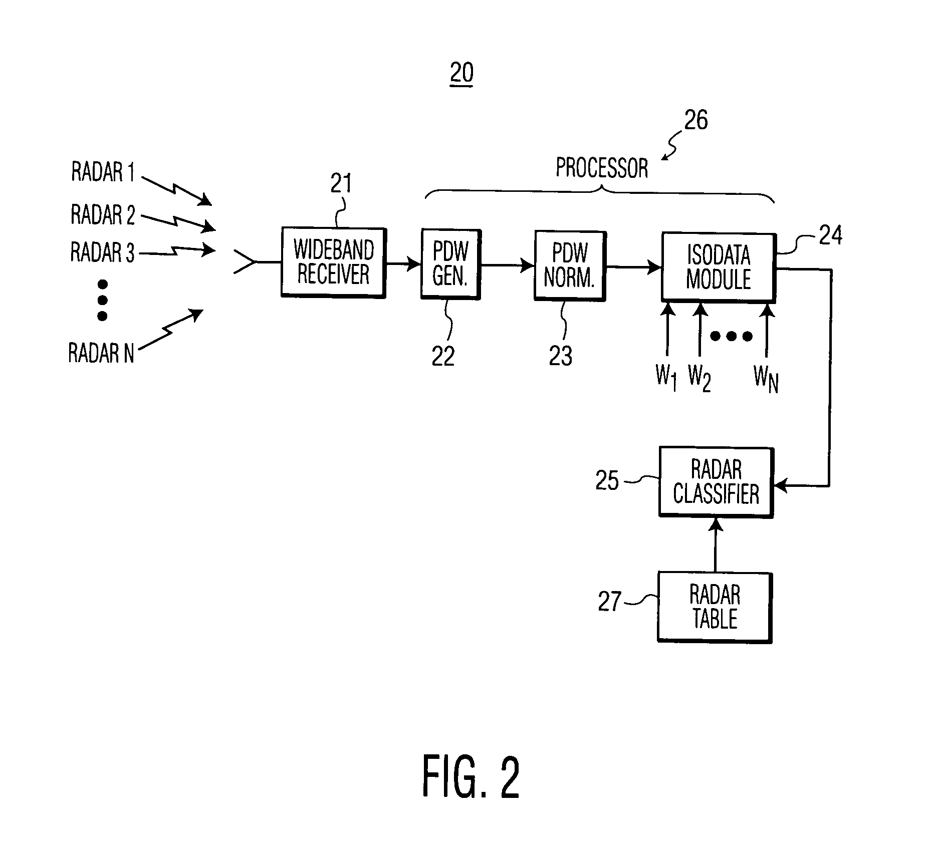
[0021]The present invention provides an unsupervised iterative classification method for radar pattern recognition. The method is self-organizing and requires minimal input from human interaction.

[0022]The method of the invention forms clusters from a set of input data (samples), where each cluster consists of very similar data (samples). The method first defines a measure of pattern similarity and establishes a rule for assigning individual samples to the domain of a specific cluster center. The invention uses the Euclidean distance between two data points x and z,

D=∥x−z∥

as a measure of pattern similarity. The smaller the distance, D, the greater is the similarity between x and z.

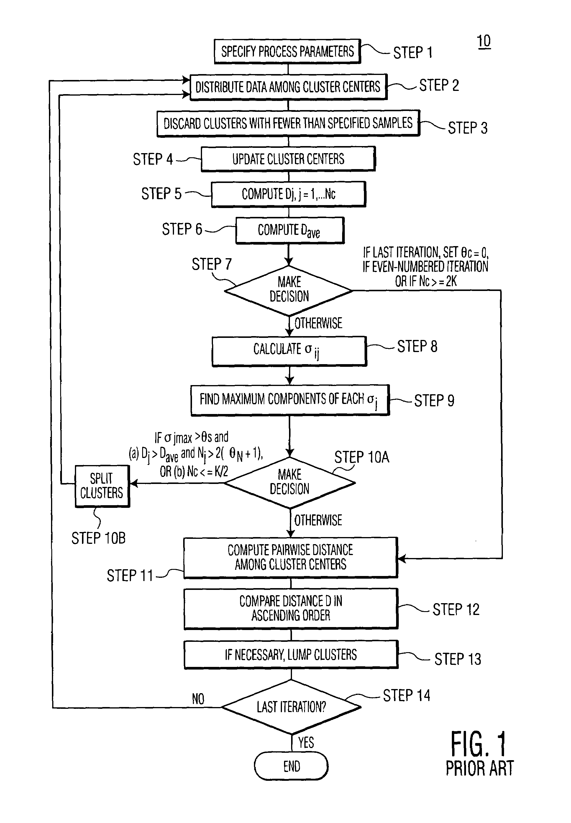
[0023]After a measure of pattern similarity is selected, the method of the invention sorts (or partitions) samples into cluster domains. The Euclidean distance measure, D, lends itself to this procedure, because it is a good measure of proximity. However, because the proximity of two patterns is a relative...


PUM


Abstract

A system and method for classifying radar emitters includes: (a) receiving a plurality of signals from the radar emitters; (b) generating data components for each signal received from the radar emitters; (c) forming multi-dimensional samples using the generated data components; and (d) sorting the multi-dimensional samples into a plurality of data clusters, based on their respective proximity to the data clusters, each data cluster representing a classification of a radar emitter.

Description

TECHNICAL FIELD[0001]The present invention relates, in general, to radar identification and, more specifically, to sorting signals received from multiple emitters into data clusters for pattern recognition.BACKGROUND OF THE INVENTION[0002]Radars emit a variety of signals that may characterize and identify them. Each radar may emit a specific pulse amplitude and a specific fixed radio frequency (RF) or a variable RF ranging over a fixed bandwidth. Each may emit a fixed pulse repetition frequency (PRF) or pulse repetition interval (PRI) and may be of a certain pulse width (PW).[0003]An aircraft flying into a region with an onboard wideband receiver may detect a variety of signals emitted from multiple radars located in that region. Unless these signals are sorted and separated from each other, it is not possible for the aircraft to determine the types of classes of radars it is about to encounter. It does not know whether the radars are hostile and does not know whether the radars pre...

Claims


Application Information

Patent Timeline
IPC IPC(8): G01S7/292G01S7/40
CPCG01S7/021
Inventor WANG, PAUL C.WARD, CHARLES R.
Owner HARRIS CORP
Why Eureka
Try Eureka