
Adaptive predistortion device and method using digital receiver

a technology of predistortion device and digital receiver, which is applied in the direction of transmitter/receiver shaping network, modulated carrier system, amplifier, etc., can solve the problems of difficult control of the effect of drift, poor power efficiency of the operating point, and critical issue of transmitter designers

Inactive Publication Date: 2006-04-25
POLYVALOR S E C
View PDF5 Cites 111 Cited by
  • Summary
  • Abstract
  • Description
  • Claims
  • Application Information

AI Technical Summary

Benefits of technology

[0016]An object of the present invention is therefore to provide an improved predistortion device and method.

Problems solved by technology

The demanding adjacent channel power ratio (hereinafter “ACPR”) requirements of these systems, i.e., W-CDMA or cdma2000, present a critical issue for transmitter designers if both ultra-linearity and high power efficiency must be met.
Therefore, for different stimulus levels driving the amplifiers and for a given ACPR specification, the trade-off between power efficiency and linearity impose an operating point with poor power efficiency.
442–428, December 1974), which includes an open loop configuration, can handle a multicarrier signal but can not easily be controlled against the effects of drift.
Moreover, their low power efficiency make it suitable in base station only.
However, stability requirement limits its bandwidth because of its critical dependence on the loop delay; and
Although the above-mentioned technique is powerful due to its digital operating principles, it presents certain inflexibility in the sense that; it is suitable only when the baseboard signal is acceded directly before the up-conversion.
In most cases, linearizer designers have no access to baseband signal; hence, they found themselves confined to use traditional Radio-frequency (hereinafter “RF”) analog predistortion techniques.
In this case, it is more difficult to meet severe ACPR for a high crest factor's signals specifications while operating not in far back-off regions.
Drawbacks of this method are its slow convergence toward the minimum and its sensitivity to the measurement noise.

Method used


Image

  • Adaptive predistortion device and method using digital receiver
  • Adaptive predistortion device and method using digital receiver
  • Adaptive predistortion device and method using digital receiver

Examples


first embodiment

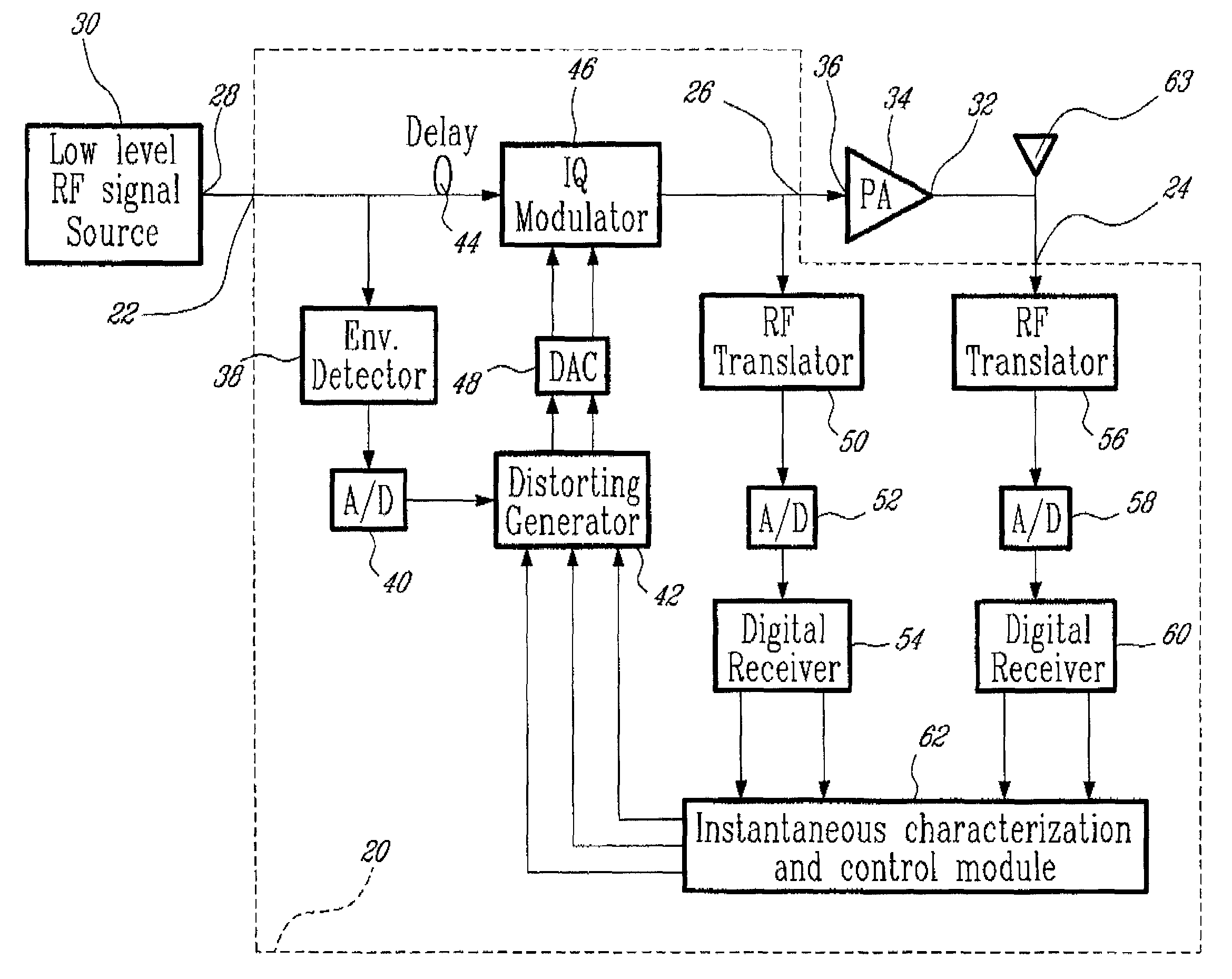
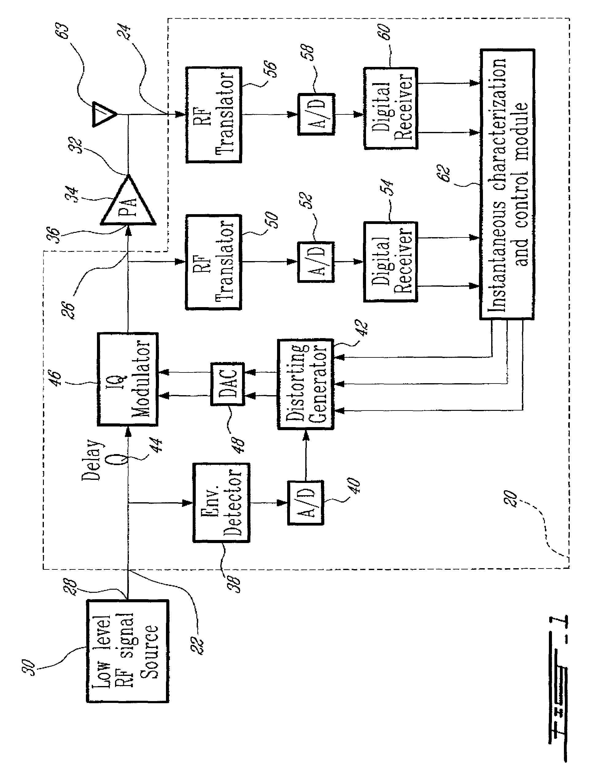
[0057]Turning now to FIG. 1 of the appended drawings, a predistorting device 20 according to the present invention will be described. The predistorting device 20 has two inputs 22 and 24 and an output 26. The first input 22 is connected to the low level RF output 28 of a low level RF signal source 30 to thereby receive an input RF signal therefrom; and the second input 24 is connected to the RF output 32 of a PA 34. The RF output 32 delivering an amplified output RF signal. The output 26, on the other hand, is connected to the input 36 of the PA 34.

[0058]The RF signal from the first input 22 goes through an envelope detector 38 to provide the envelope variation thereof. This envelope is digitized by an analog to digital converter (hereinafter “A / D”) 40. The digitized envelope is used to index a distorting generator 42 as will be described hereinbelow.

[0059]The RF signal from the first input 22 also goes through a delay line 44 and then in an Quadrature modulator 46 (hereinafter refe...

second embodiment

[0116]Turning now to FIG. 13 of the appended drawings, a predistorting device 100 according to the present invention will be described. It is to be noted that the same reference numeral are used to refer to the same elements. It is also to be noted that the predistorting device 100 is very similar to the predistorting device 20 and therefore, for concision purposes, only the difference therebetween will be discussed hereinbelow.

[0117]Basically, the envelope detector 38 and the A / D converter 40 used to index the distorting generator 42 of the predistorting device 20 have been replaced by a third RF translator 102, A / D converter 104 and third digital receiver 106 route. The output of the digital receiver 106 is supplied to the instantaneous characterization and control module 62 which is used to index the distorting generator 42 as previously discussed. The other elements and the operation of the predistorting device 100 are identical to the predistorting device 20.

[0118]This predisto...


PUM


Abstract

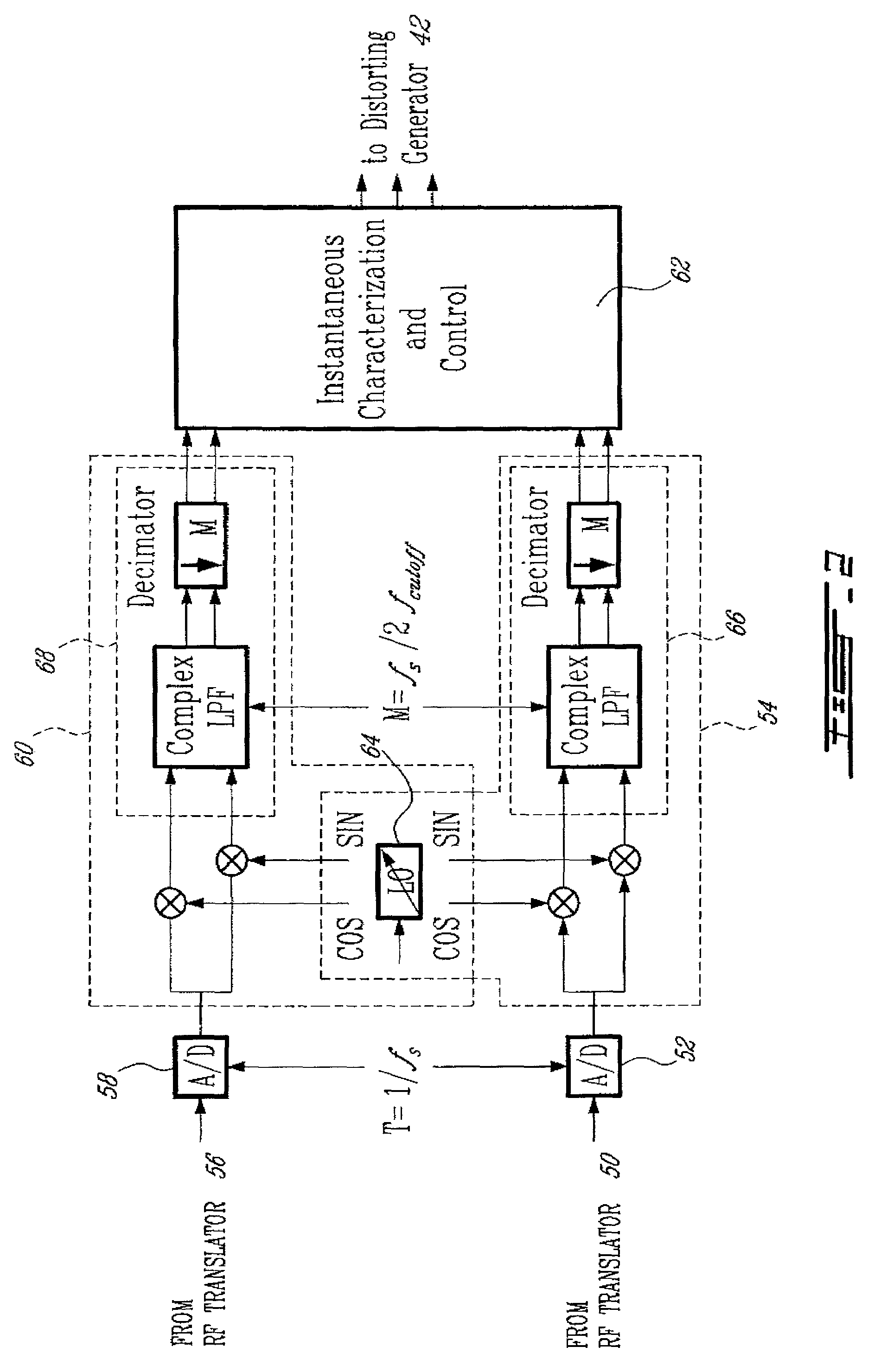
An advanced adaptive baseband / RF predistorting device, which advantageously uses the concept of digital receiver technology into power amplifier (PA) linearization area. The predistorting device performs an instantaneous characterization of the PA using two digital receivers to supply its dynamic AM-AM and AM-PM transfer functions used to synthesize Look-Up Tables (LUT) which implement the complex predistortion function in order to compensate for any non-linearity and memory effects.

Description

FIELD OF THE INVENTION[0001]The present invention relates to predistorting devices. More specifically, the present invention is concerned with a predistorting device and to a method of predistortion using digital receivers.BACKGROUND OF THE INVENTION[0002]The demand for developing ultra-linear microwave transmitter, supporting high crest factor signals, increases rapidly, for example by the definition of the third generation (hereinafter “3G”) of mobile radio standards.[0003]The demanding adjacent channel power ratio (hereinafter “ACPR”) requirements of these systems, i.e., W-CDMA or cdma2000, present a critical issue for transmitter designers if both ultra-linearity and high power efficiency must be met. In fact, the degradation of linearity becomes significant as the power amplifier (hereinafter “PA”) operates close to saturation where both high power efficiency and high output power emission are achieved. Therefore, for different stimulus levels driving the amplifiers and for a g...

Claims


Application Information

Patent Timeline
Patent Type & Authority Patents(United States)
IPC IPC(8): H04K1/02H03F1/32
CPCH03F1/3247H03F1/3294H03F2200/102
Inventor JECKELN, ERNESTO G.GHANNOUCHI, FADHEL M.SAWAN, MOHAMADBEAUREGARD, FRANCOIS
Owner POLYVALOR S E C
Learn More