Flying insect trap

a technology for flying insects and traps, which is applied in the field of flying insect traps, can solve the problems of preventing the direct view of the complete lamp at normal mounting height, and achieve the effect of enhancing insect attraction

Active Publication Date: 2006-05-02
PARACLIPSE SYST
View PDF71 Cites 20 Cited by
  • Summary
  • Abstract
  • Description
  • Claims
  • Application Information

AI Technical Summary

Benefits of technology

[0007]The present invention includes a housing which is curved into a concave shape, closed on three sides and bottom with an open top and, if desired, an open back. The housing encloses the light source and the trapping medium. This prevents a direct view of the complete lamps at normal mounting heights and lower. The upper front portion of the housing includes a series of groups of narrow slits to permit a direct partial viewing of the light source from a large area of the room in which it is mounted to enhance insect attraction. The inside surface of the housing may be black (i.e. non-reflecting) or a light or white color, or it may be provided with a reflective surface such as metallized Mylar to reflect light upwardly through the top opening of the housing onto a cover mounted above the housing.
[0008]The cover is positioned to intercept all light directly from the source as well as all reflected light from within the housing which would otherwise impinge on the wall on which the unit is mounted. To accomplish this, the cover has a shape of a band shell to intercept direct and reflected light and direct all of the incident light from the source, both direct and reflected, out in front of the unit. At least a portion of the light reflected by the cover is directed downwardly in front of the unit. The cover is shaped and positioned relative to the light source so that it prevents light, both direct and reflected, from shining on the wall above the housing. Thus, the attractant light display of the instant unit is located on the cover, and the unit is said to be independent of the wall in this respect.
[0010]With the present invention, no perceptible amount of light is transmitted directly or indirectly to the wall on which the unit is mounted, thereby preserving any coating or covering on the wall from damage which may otherwise result from the ultraviolet light.

Problems solved by technology

This prevents a direct view of the complete lamps at normal mounting heights and lower.

Method used


Image

  • Flying insect trap
  • Flying insect trap
  • Flying insect trap

Examples


Embodiment Construction

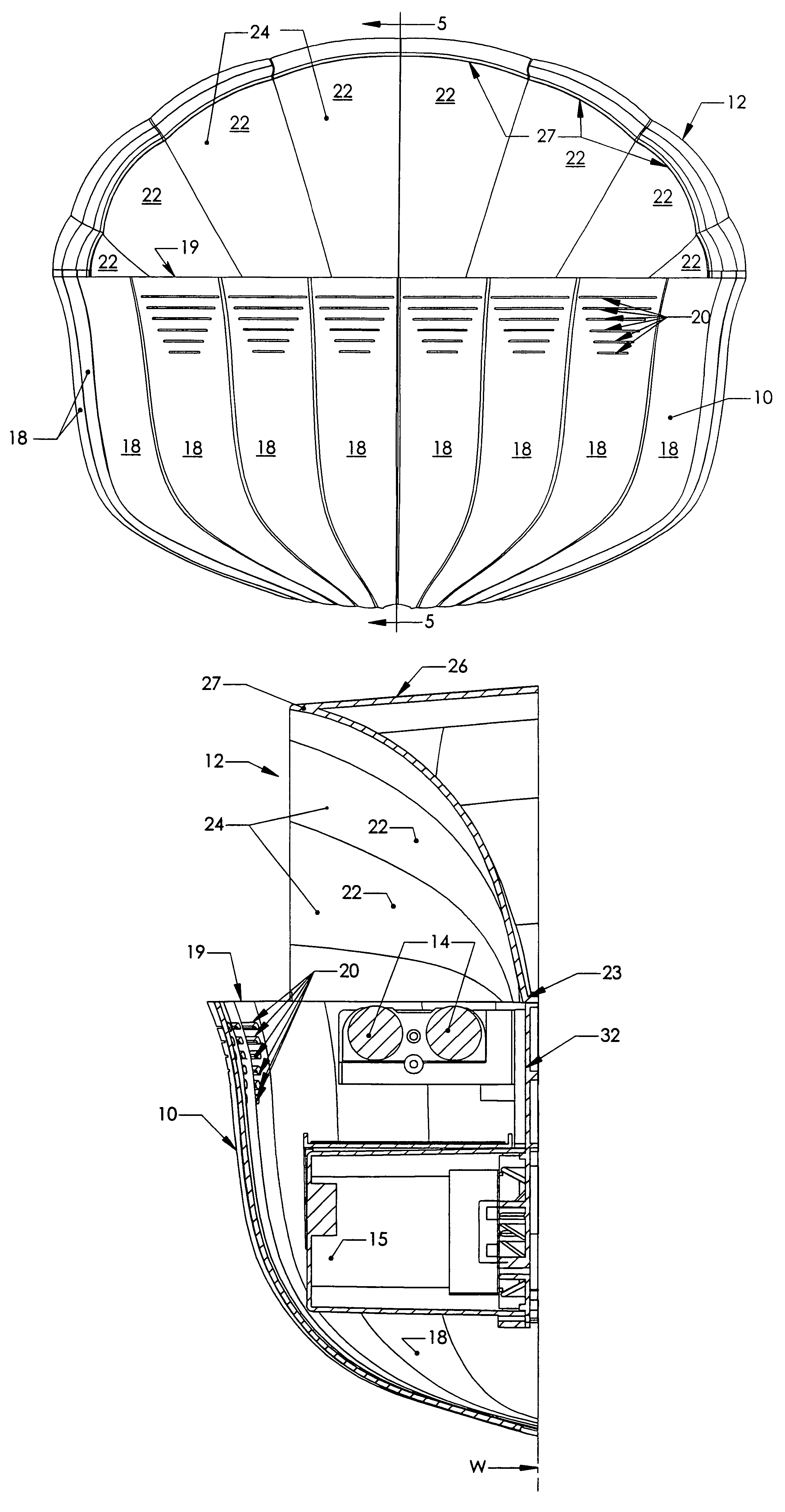
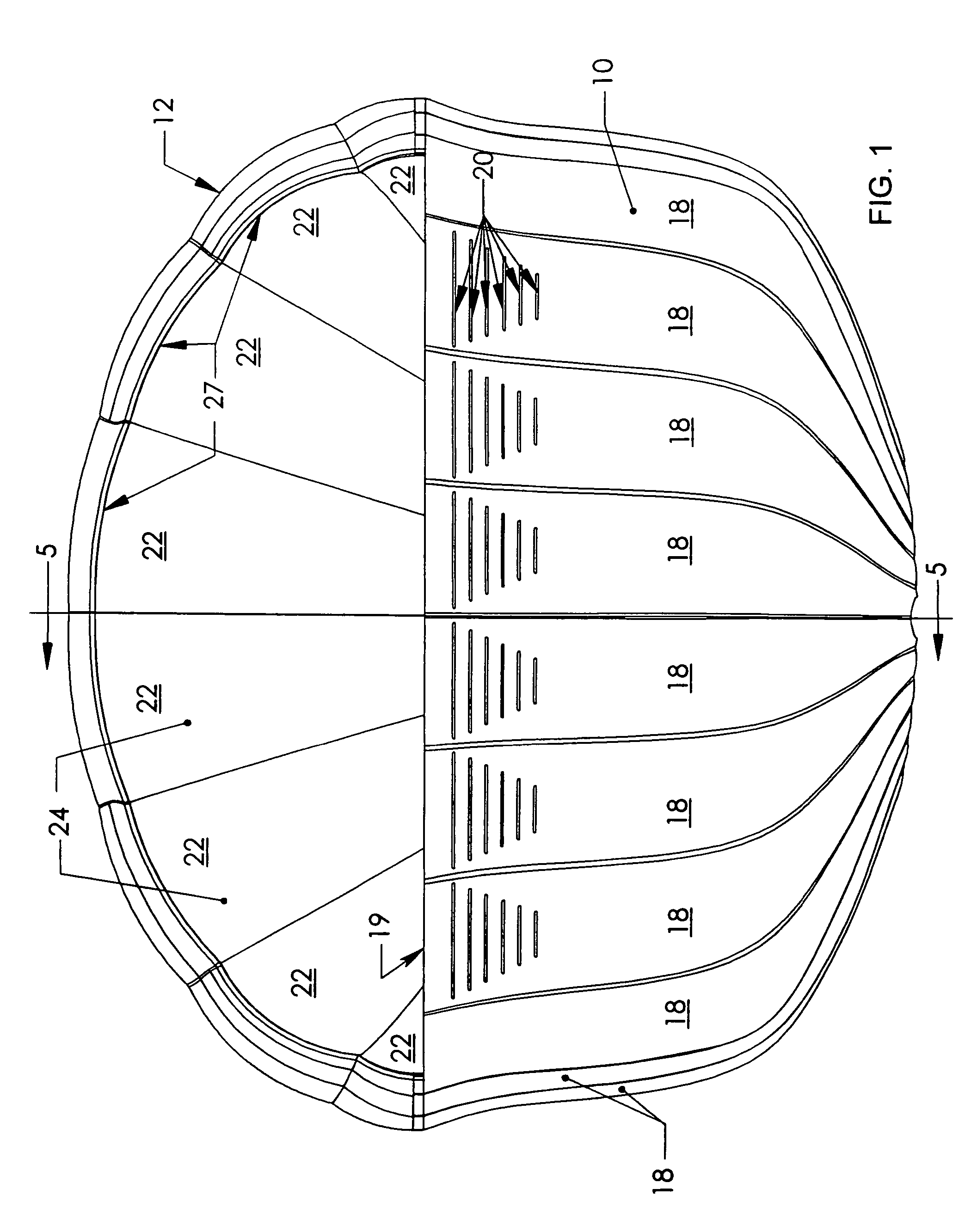
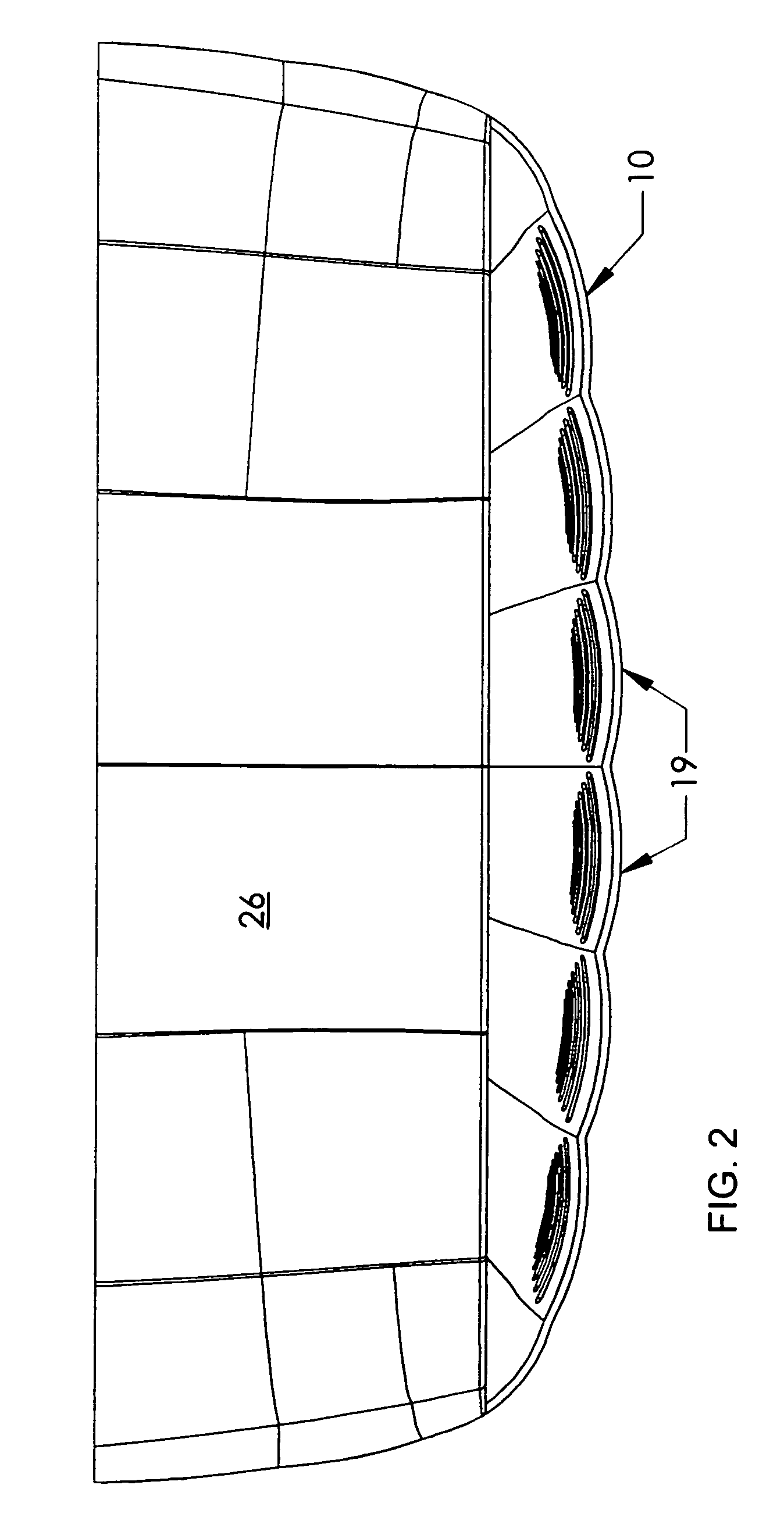
[0018]Referring now to the drawing, it will be helpful in obtaining an overall understanding of the invention to identify the major components. These include a housing generally designated by reference numeral 10. The housing 10, as best seen from FIGS. 1, 2, 3 and 5 has a generally curved, concave shape having closed bottom, sides and front (except for the light slits to be described), and an open top and open back. Mounted above the housing 10 is a cover generally designated 12, and best seen in FIGS. 1–6. The housing 10 and cover 12 may each be integrally molded from a suitable plastic material such as polystyrene (impact) or other suitable plastics; and these two elements may be coupled together and mounted to a mounting plate 32 (FIGS. 5 and 6) which is secured with suitable fasteners to a wall designated W in FIG. 5 to form an integral unit, as will further be described within.

[0019]Referring for a moment to FIGS. 5 and 6, enclosed by the housing 10 are a pair of flourescent l...


PUM


Abstract

A flying inspect trap has a source of UV light to attract insects and an adhesive sheet to trap them. A concave housing which encloses the light source and the trapping medium has a series of narrow light-transmissive slits in a front wall to permit a direct partial viewing of the source from the front of the unit to enhance insect attraction. A cover mounted above the housing has a reflecting surface in the form of a band shell which reflects light from the source out into the room as well as downwardly in front of the unit, and prevents light from shining directly or indirectly on the wall above the housing.

Description

RELATED APPLICATIONS[0001]Applicant claims the benefit of provisional application Ser. No. 60 / 467,074 for “FLYING INSECT TRAP”, filed Apr. 30, 2003.FIELD OF THE INVENTION[0002]The present invention relates to traps for flying insects of the type using an ultraviolet light source to attract insects, and an adhesive sheet or paper to trap them.BACKGROUND OF THE INVENTION[0003]There have been a number of designs for wall-mounted flying insect traps suitable for use, for example, in the dining area of a restaurant, as distinguished from the food preparation area of the restaurant. Units designed for the dining area are typically wall-mounted, and take the form of a wall sconce so that they appear, in general, to be a decorative wall light to a customer rather than an insect trap.[0004]Since it is known that ultraviolet light attracts flies better than a conventional light source, ultraviolet light sources are typically used in such units, whether they are designed for use in the dining ...

Claims


Application Information

Patent Timeline
Patent Type & Authority Patents(United States)
IPC IPC(8): A01M1/04A01M1/14
CPCA01M1/145A01M2200/012
Inventor TAYLOR, LARRY R.LAMBERT, C. RONALD
Owner PARACLIPSE SYST
Why Eureka
Try Eureka