Fuel cell stack humidification device

a technology of fuel cell and stack, which is applied in the direction of fuel cell details, transportation hydrogen technology, electrochemical generators, etc., can solve the problems of increasing the output of the fuel cell, difficulty in controlling water, and fast start-up time of the pem fuel cell for power conversion, so as to increase the capillary attraction

Inactive Publication Date: 2009-08-20
HYUNDAI MOTOR CO LTD
View PDF2 Cites 7 Cited by
  • Summary
  • Abstract
  • Description
  • Claims
  • Application Information

AI Technical Summary

Benefits of technology

[0029]In another preferred embodiment, the water absorbing member is formed of porous polyvinyl alcohol (PVA) sponge

Problems solved by technology

The PEM fuel cell has a fast start-up time and a fast reaction time for power conversion due to its low operation temperature.
However, the PEM fuel cell has problems in that it requires an expensive catalyst, causes catalyst poisoning, and has a difficulty in controlling water.
When pure oxygen is used, the output of the fuel cell is increased; however, since the volume of an oxygen tank is greater than that of the hydrogen tank, it is not economical to mount the oxygen tank together with the hydrogen tank in the vehicle.
Meanwhile, if the PEM is excessively wetted, pores of a gas diffusion layer (GDL) are clogged, and thus the reactant gas is not in contact with the catalyst.
However, the above membrane humidifier has some disadvantages in that the exchange membrane

Method used


Image

  • Fuel cell stack humidification device
  • Fuel cell stack humidification device
  • Fuel cell stack humidification device

Examples


Embodiment Construction

[0043]Reference will now be made in detail to the preferred embodiments of the present invention, examples of which are illustrated in the drawings attached hereinafter, wherein like reference numerals refer to like elements throughout. The embodiments are described below so as to explain the present invention by referring to the figures.

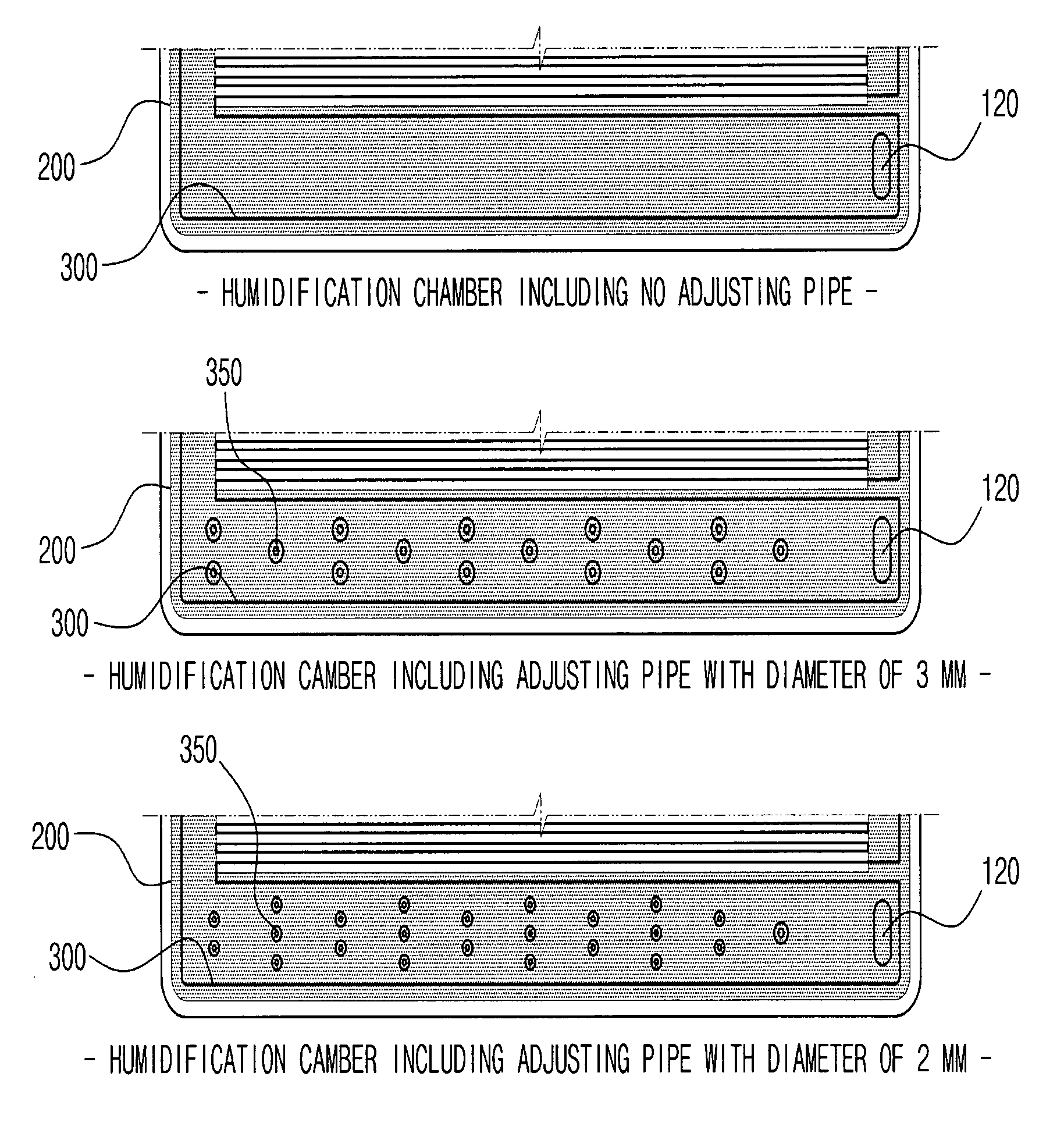
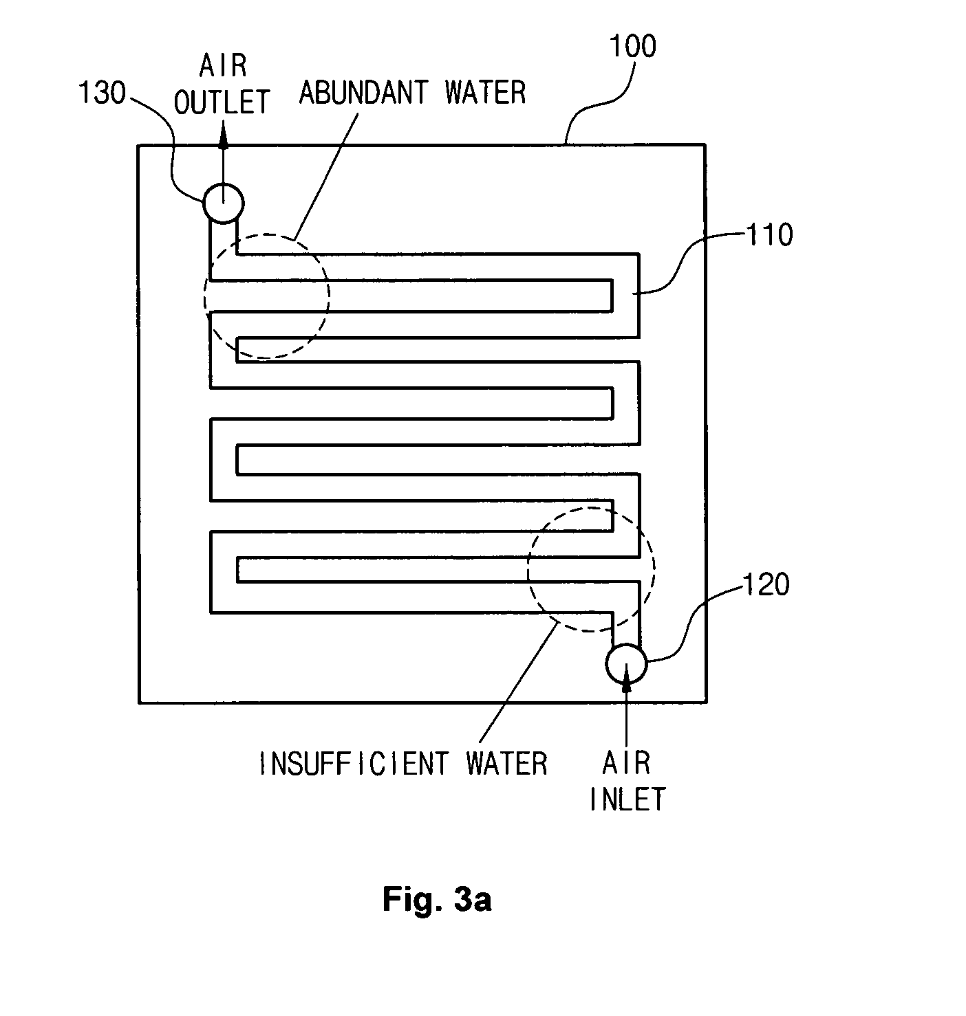
[0044]As shown in FIG. 3B, a fuel cell stack humidification device includes an air flow field 110 mounted on a fuel cell separator 100 and a water absorbing member 200 provided on both sides and the bottom of the air flow field 110. The water absorbing member 200 is formed of a porous material, which transfers water present in an outlet portion 130 of the air flow field 110 to an inlet portion 120 by capillary attraction and gravity, thus increasing the humidity of the inlet portion 120 and minimizing the volume that a humidifier occupies in a fuel cell vehicle.

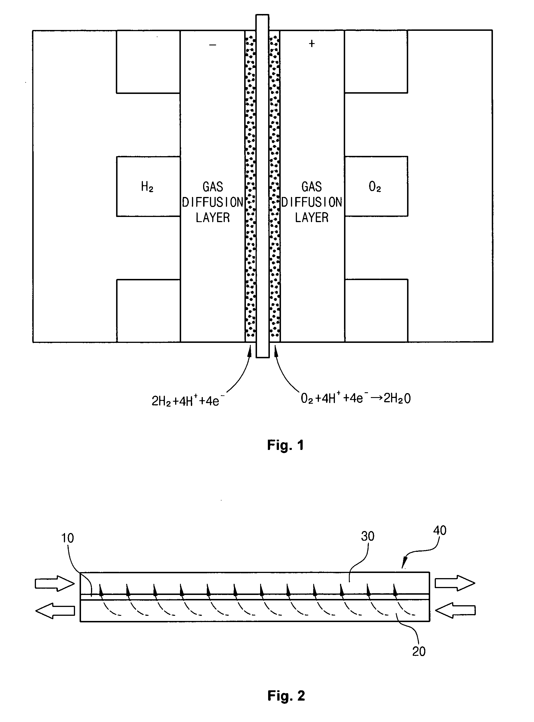
[0045]In the outlet portion 130 in a PEM fuel cell, water generated by a reaction in the ...


PUM


Abstract

A fuel cell stack humidification device includes: an air flow field provided on a fuel cell separator and including an inlet portion and an outlet portion; and a water absorbing member mounted on both sides and the bottom of the air flow field to transfer water in the outlet portion to the inlet portion. The humidification device can provide an auxiliary humidification function and minimize the volume that a humidifier occupies in a fuel cell vehicle.

Description

CROSS-REFERENCE TO RELATED APPLICATION[0001]This application claims under 35 U.S.C. §119(a) the benefit of Korean Patent Application No. 10-2008-0013413 filed Feb. 14, 2008, the entire contents of which are incorporated herein by reference.BACKGROUND[0002](a) Technical Field[0003]The present invention relates to a fuel cell stack humidification device. More particularly, the present invention relates to a fuel cell stack humidification device including an air flow field mounted on a fuel cell separator and a water absorbing member provided on both sides and the bottom of an air flow field, which can provide an auxiliary humidification function to increase the humidity of an inlet portion of the air flow filed.[0004](b) Background Art[0005]Typically, vehicles are driven by a fossil fueled engine. Carbon dioxide is produced and emitted as gas when fossil fuels are burned, which contributes to global warming. Numerous fossil fuel substitutes have been studied, and a hydrogen fuel cell ...

Claims


Application Information

Patent Timeline
IPC IPC(8): H01M8/04
CPCH01M8/0263H01M8/04141H01M8/04149Y02E60/50H01M2008/1095H01M2250/20Y02T90/32H01M8/04171Y02T90/40H01M8/02H01M8/04
Inventor KIM, HYUN YOOPARK, YONG SUNKWON, HYUCK ROULKIM, MIN SOOSONG, JUN HOKIM, BEOM JUN
Owner HYUNDAI MOTOR CO LTD
Why Eureka
Try Eureka