
Free cooling activation optimized controls

a technology of activation and control, applied in the direction of domestic cooling apparatus, lighting and heating apparatus, heating types, etc., can solve the problems of low efficiency of air cooling, unstable operation, and difficulty in estimating the optimum outdoor temperatur

Active Publication Date: 2006-05-02
CARRIER CORP
View PDF5 Cites 26 Cited by
  • Summary
  • Abstract
  • Description
  • Claims
  • Application Information

AI Technical Summary

Benefits of technology

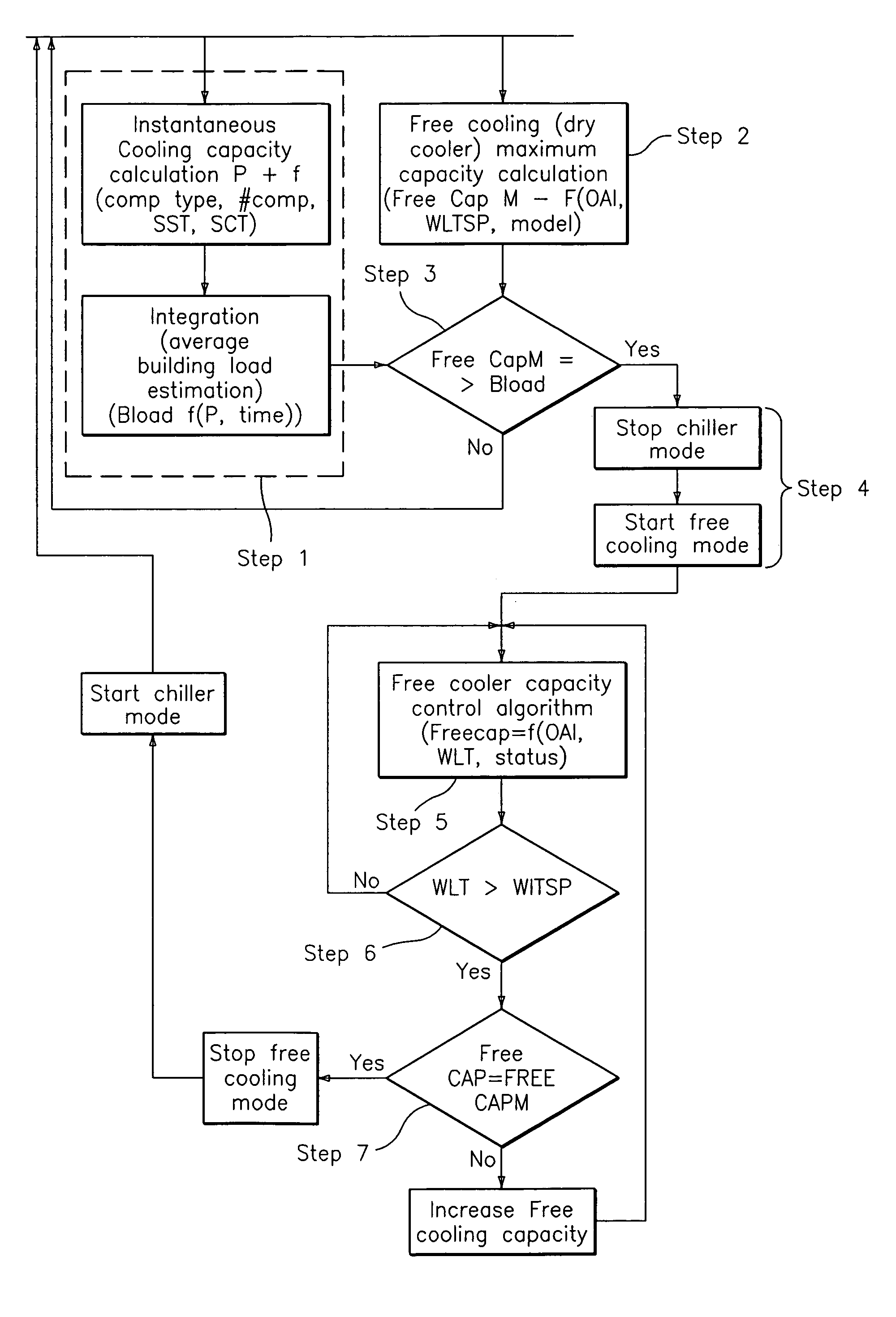
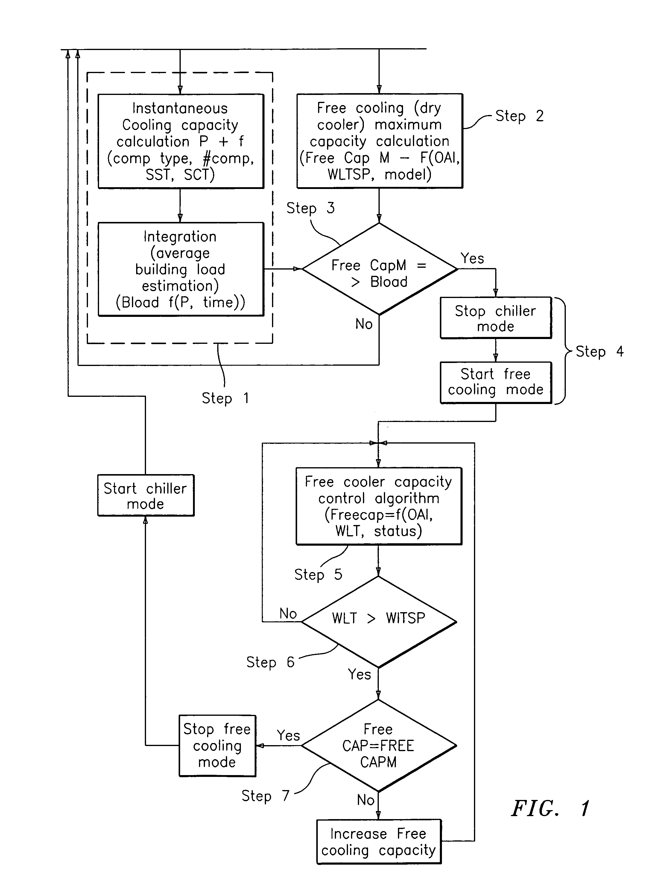
The present invention provides a method for optimizing the point at which an air conditioning unit switches between operating in a chiller mode and operating in a free cooling mode. The method involves operating the air conditioning unit in a chiller mode, determining the building load, determining the maximum available capacity of the free cooler, and activating the free cooling mode when the maximum available capacity is greater than or equal to the building load. This method helps to improve the efficiency of the air conditioning unit and save energy during cooling season.

Problems solved by technology

Running in chiller mode under such conditions provides a low efficiency means of air cooling.
Unfortunately, it is difficult to estimate the optimum outdoor temperature at which free cooling may be most effectively and efficiently utilized.
One problem arising when trying to determine the optimum outdoor temperature at which an air conditioning unit should switch from chiller mode to free cooling mode arises from the fact that free cooler capacity is directly related to outdoor air temperature while a building load may not be.
If this arbitrary temperature is not in phase with the actual needs of cooling the building, there can result an unstable operation.
Specifically, there may be encountered a situation wherein there occurs rapid switching back and forth between free cooling mode and chiller mode.
In addition, it may arise that cooling is performed in a non-optimum manner such as when the air conditioning unit is run in chiller mode when free cooler mode is both available and preferable.

Method used


Image

  • Free cooling activation optimized controls
  • Free cooling activation optimized controls

Examples


Embodiment Construction

[0014]It is therefore a teaching of the present invention to provide a method for determining an optimum, or near optimum point at which an air conditioning unit should switch between operating in a chiller mode and operating in a free cooling mode. In order to do this, the present invention teaches the dynamic identification of such a switch point derived from a real time determination of both the building load and the free cooler maximum available capacity. As shall be detailed below, the method of the present invention consists of a dynamic estimation of both the building load and the free cooler maximum available capacity so as to determine an optimal point at which one should switch between a chiller mode and a free cooling mode operation.

[0015]Estimations of the building load and free cooler capacity are based on mathematical models of the chiller and dry cooler hardware and available parameters which are, for a chiller: SST (saturated suction temperature) and SCT (saturated c...


PUM


Abstract

A method for optimizing free cooling activation comprising the steps of operating an air conditioning unit in a chiller mode, determining a building load, determining a free cooler maximum available capacity (FreeCapM), and activating a free cooling mode of the air conditioning unit when the free cooler maximum available capacity is greater than or equal to the building load.

Description

BACKGROUND OF THE INVENTION[0001](1) Field of the Invention[0002]The invention relates to a method for optimizing the point at which an air conditioning unit is switched between operating in a chiller mode to operating in a free cooling mode.[0003](2) Description of the Related Art[0004]During the typical operation of air conditioning units, the air conditioning unit is run in a chiller mode wherein energy is expended to chill the air within a volume to be cooled. However, when the ambient temperature is low, there exists the possibility that such a low temperature ambient air may be utilized to provide cooling without engaging in a chiller mode. When low temperature ambient air is used by an air conditioning unit to cool a space, the unit is referred to as operating in a free cooling mode. As noted above, traditionally, even when ambient air temperature is low, the air conditioning unit is run in a chiller mode. Running in chiller mode under such conditions provides a low efficienc...

Claims


Application Information

Patent Timeline
Patent Type & Authority Patents(United States)
IPC IPC(8): F25D17/02F25B25/00F24F11/00F25D16/00F25D17/00
CPCF24F11/006F24F2011/0006F24F2011/0013Y10S62/22F25B2700/2106F25D16/00Y02B30/542F24F2011/0045F24F11/30F24F2110/12F24F2140/20F24F11/62Y02B30/54
Inventor GRABON, MICHAL K.BALLET, JOSEPH
Owner CARRIER CORP
Learn More