Directing sound field of actuator

一种驱动器、静电驱动器的技术,应用在传感器、换能器电路、静电传感器等方向,能够解决提高系统复杂度、增加元件等问题,达到简化结构和控制部件、减少元件的数量、优化数量的效果

Inactive Publication Date: 2011-04-06
PANPHONICS OY
View PDF6 Cites 0 Cited by
  • Summary
  • Abstract
  • Description
  • Claims
  • Application Information

AI Technical Summary

Problems solved by technology

However, both solutions require separate delay devices or circuits in order to create delays for different parts of the diaphragm or different vibrators, which adds a large number of components and increases the complexity of the system

Method used


Image

  • Directing sound field of actuator
  • Directing sound field of actuator
  • Directing sound field of actuator

Examples


Embodiment Construction

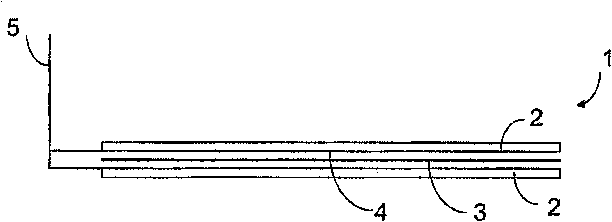
[0021] figure 1 Schematic diagram of the structure of an electrostatic driver, such as a loudspeaker. The electrostatic driver 1 includes at least one plate-shaped stator 2 and a movable diaphragm 3 . exist figure 1 In the shown embodiment there are two stators 2 between which the movable diaphragm 3 is arranged. Electrodes 4 are formed on the surface of the stator 2 . The signal is transmitted along the signal line 5 to the electrodes.

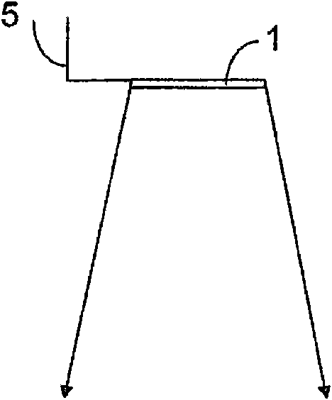
[0022] figure 2 The sound field formed by the electrostatic driver in the prior art is shown. In the solution of the prior art, the conductivity of the electrode 4 is very good, that is, the surface 4 of the stator 2 is conductive, such as a metal coating. In practice, there is no propagation delay for signals in electrostatic drivers, even when the signals are input at the edges of the driver. This forms as figure 2 sound field shown.

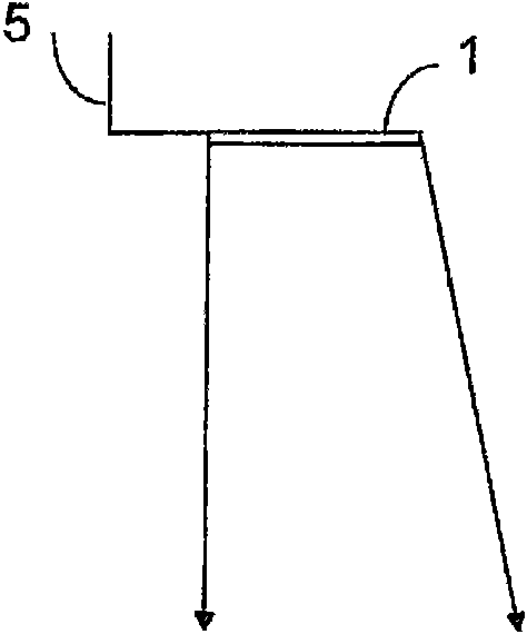
[0023] image 3 and Figure 4 It is a schematic diagram of a directional sound field formed b...


PUM


Abstract

The invention relates to a plate-like electrostatic actuator which comprises at least one plate-like stator (2) with an electrode (4) formed on its surface and at least one moving diaphragm (3), and in which a signal is transmitted to the electrode along a signal line (5). In the solution of the invention, the delay directing the sound field of the actuator is formed at least partly of an RC circuit composed of components of the actuator.

Description

technical field [0001] The invention relates to a plate-shaped electrostatic driver, which includes at least one plate-shaped stator with electrodes formed on its surface and at least one movable diaphragm, wherein signals are transmitted to the electrodes along signal lines. [0002] The present invention further relates to a method for orienting the sound field of a plate-shaped electrostatic driver comprising at least one plate-shaped stator and at least one movable diaphragm with electrodes formed on its surface, wherein signals are transmitted to the electrodes along signal lines . Background technique [0003] At present, the orientation of the radiated sound field is generally achieved by forming several sound sources and supplying signals to each sound source with different delays and / or signal amplitudes. Delay and frequency filtering of signals are established using constant value or adjustable RC circuits, or via multi-channel analog or digital signal processing....

Claims


Application Information

Patent Timeline
Patent Type & Authority Applications(China)
IPC IPC(8): H04R19/00H04R1/34
CPCH04R3/00H04R19/00H04R19/02
Inventor A·凯龙尼米E·洪卡科斯基P·派特拉
Owner PANPHONICS OY
Why Eureka
Try Eureka