Dispenser device for fitting to a receptacle provided with a valve

a dispenser device and valve technology, applied in the direction of liquid handling, instruments, closures using stoppers, etc., can solve the problems of unsuitable use of such receptacles and relatively high features, and achieve the effect of reliable dispensers and low cos

Inactive Publication Date: 2006-05-02
LOREAL SA
View PDF26 Cites 56 Cited by
  • Summary
  • Abstract
  • Description
  • Claims
  • Application Information

AI Technical Summary

Benefits of technology

[0010]The invention makes it possible to provide at relatively low cost a reliable dispenser device that can be used with a dispenser, element, such as a valve or a pump, that requires only a small displacement of a control rod in order to cause the substance to be dispensed.

Problems solved by technology

However, there exist numerous pressurized receptacles that are fitted with valves that require the valve rod to travel over a short stroke only in order to cause the substance to be dispensed, and as a result the device described in FR-A-2 814 726 is unsuitable for use with such receptacles.
The device described in FR 1 572 537 uses a metal spring to act on the dispenser endpiece, but that feature is relatively expensive.

Method used


Image

  • Dispenser device for fitting to a receptacle provided with a valve
  • Dispenser device for fitting to a receptacle provided with a valve
  • Dispenser device for fitting to a receptacle provided with a valve

Examples


Embodiment Construction

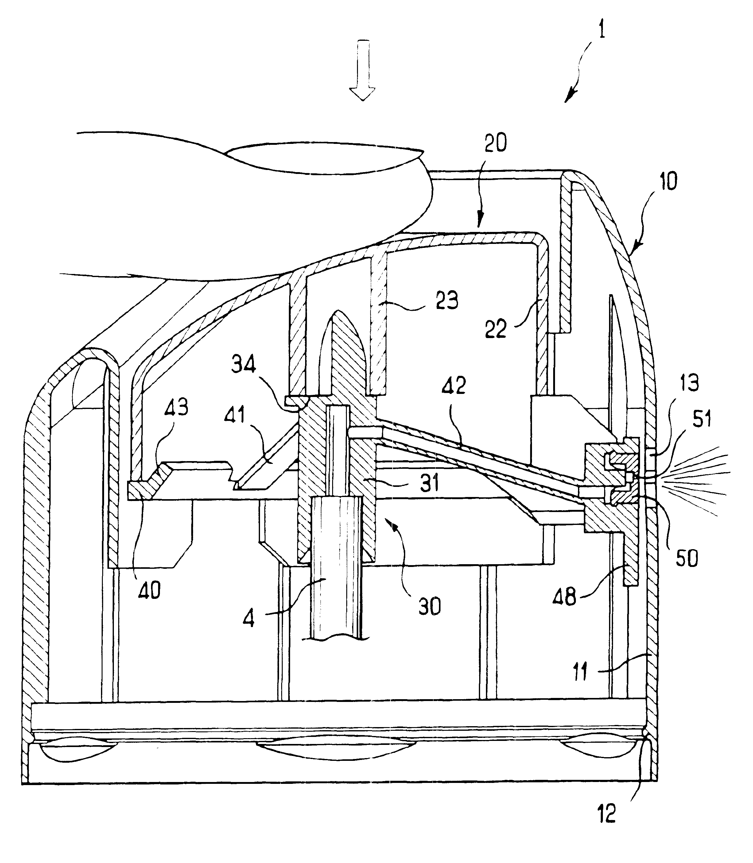
[0033]The drawings show a dispenser device 1 for fitting on a receptacle 2, the receptacle being shown in part in FIGS. 3 and 4.

[0034]In one embodiment, the receptacle 2 comprises a pressurized can 3 provided with a valve 90 crimped in a cup closing the top portion of the can 3 in a conventional manner, the valve 90 having a hollow valve rod 4.

[0035]The valve may be of any known type, with actuation being performed, in one embodiment, by depressing the rod 4 over a stroke of not more than 2 mm.

[0036]The receptacle 2 may contain a substance for spraying, e.g. a cosmetic, together with a propellent gas, which may optionally be stored in liquefied form in the receptacle 2 and may optionally be delivered together with the substance.

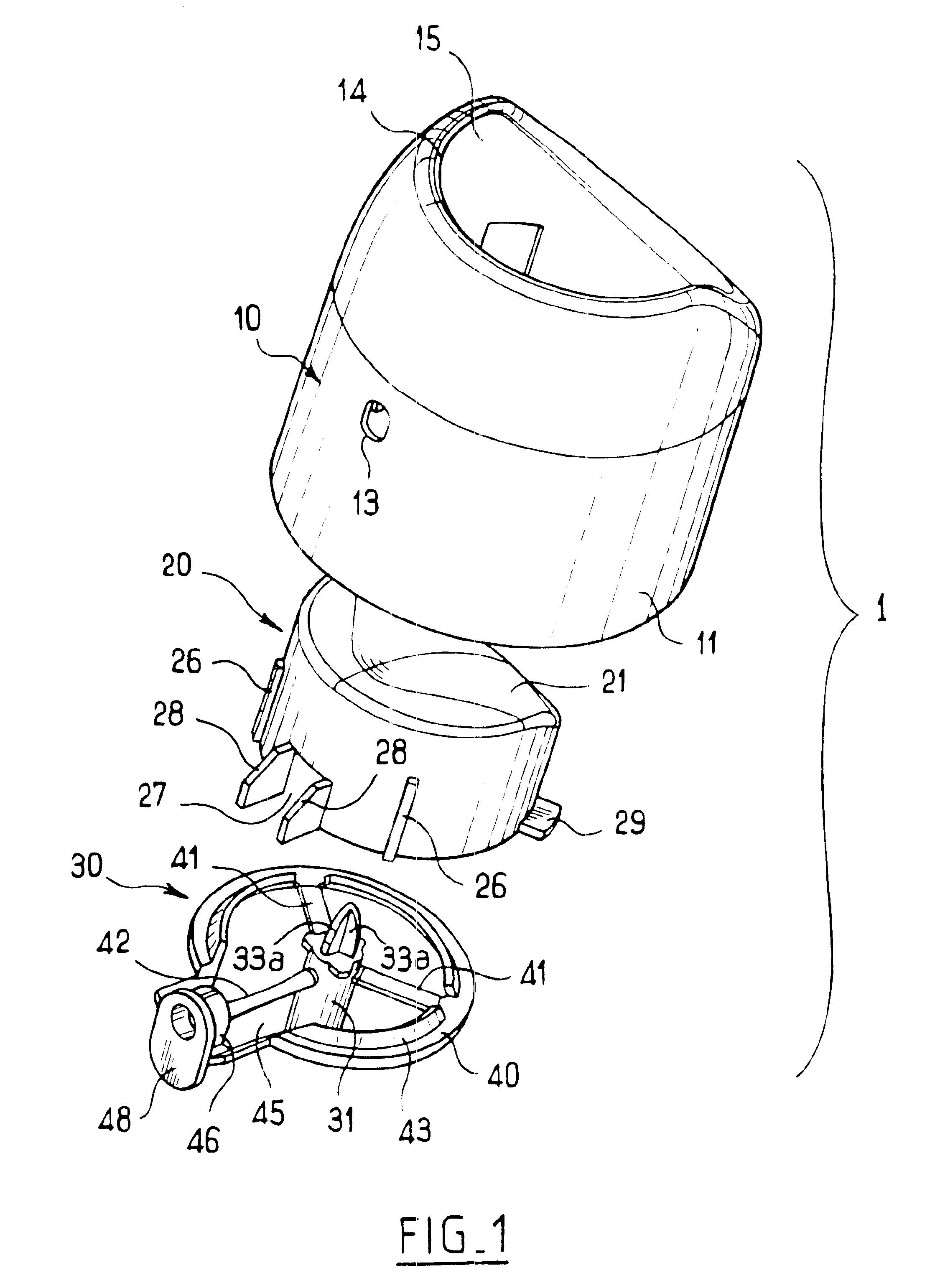
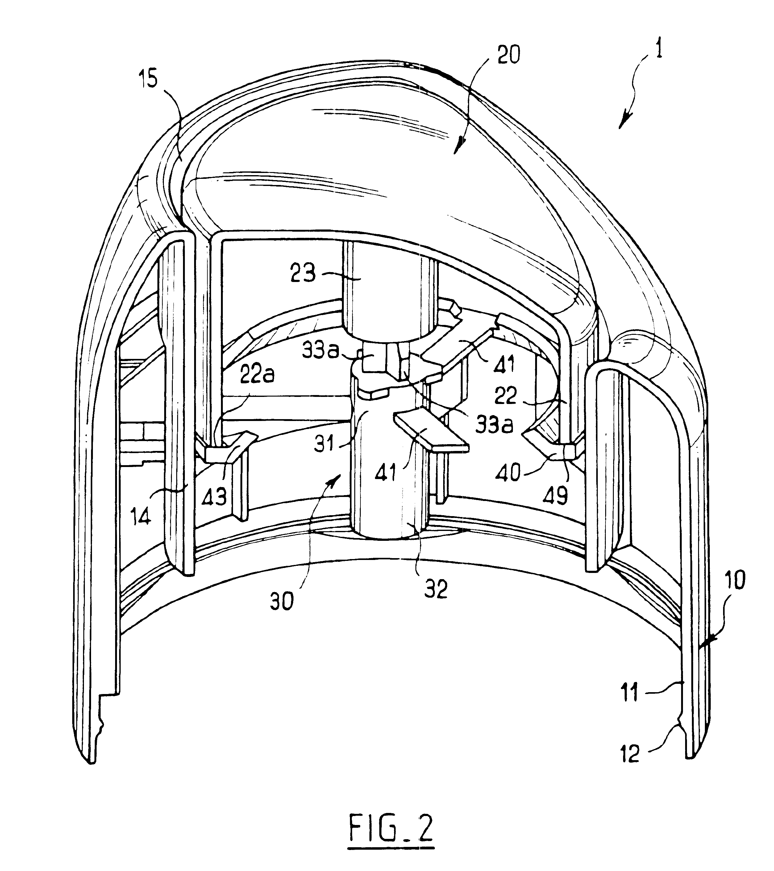
[0037]The dispenser device 1 comprises a cover 10, a pushbutton 20, and a dispenser endpiece 30.

[0038]The cover 10 has an assembly skirt 11 provided at its bottom end with a bead 12 suitable for snap-fastening in an annular groove 5 present near the top of th...


PUM


Abstract

The present invention relates to a dispenser device having: a cover; a dispenser endpiece, the dispenser endpiece having a dispenser orifice and a duct for channeling the substance flowing out from the dispenser element towards the dispenser orifice; and a pushbutton movable relative to the cover. The pushbutton is configured so that when actuated to dispense the substance, it in a first stage moves the dispenser orifice relative to the cover in such a manner as to bring it into register with the opening of the cover, the duct of the dispenser endpiece being suitable for deforming so as to enable the dispenser orifice to be moved without actuating the dispenser element during this first stage; and thereafter, in a second stage, it actuates the dispenser element.

Description

RELATED APPLICATIONS[0001]This application claims priority to French Patent Application No. 02 06362 filed May 24, 2002, which is incorporated herein by reference.FIELD OF THE INVENTION[0002]The present invention relates to dispenser devices.BACKGROUND OF THE INVENTIONS.[0003]A dispenser device is known from FR-A-2 814 726, but is suitable for operating only with a valve that enables the rod of the valve to be depressed over a considerable stroke prior to triggering dispensing of the substance.[0004]However, there exist numerous pressurized receptacles that are fitted with valves that require the valve rod to travel over a short stroke only in order to cause the substance to be dispensed, and as a result the device described in FR-A-2 814 726 is unsuitable for use with such receptacles.[0005]Other dispenser devices are known from WO 97 / 25259, EP-A-1 118 554, FR-A-2 767 799, EP-A-0 151 973, CH 422 168, and FR 1 572 537.[0006]The device described in FR 1 572 537 uses a metal spring to...

Claims


Application Information

Patent Timeline
Patent Type & Authority Patents(United States)
IPC IPC(8): B65D88/54B05B11/00B65D47/34B65D83/16
CPCB65D83/206B05B11/3015B65D83/205B05B11/1015
Inventor NICOLAS, ALBISETTI
Owner LOREAL SA
Why Eureka
Try Eureka