
Printing method and apparatus for back-up of defective marking elements

a marking element and printing method technology, applied in printing, other printing apparatus, etc., can solve the problems of printing showing defects that can run throughout printing, formation of artefacts, and constraints on the quality of the drives used

Inactive Publication Date: 2006-05-02
AGFA GEVAERT AG
View PDF13 Cites 8 Cited by
  • Summary
  • Abstract
  • Description
  • Claims
  • Application Information

AI Technical Summary

Benefits of technology

[0018]if a pre-set number of equivalent marking elements of the set of equivalent marking elements are defective, reconfiguring the printing head so that other sets of at least first and second equivalent marking elements are determined. This pre-set number may include all equivalent marking elements of the set of equivalent marking elements, or less.

Problems solved by technology

A small dot spacing in the slow scan direction means a small distance between marker elements on the head, whereas regularly spaced dots at a small distance in the fast scan direction places constraints on the quality of the drives used to move the printing head relative to the printing medium in the fast scan direction.
One general problem of dot matrix printing is the formation of artefacts caused by the digital nature of the image representation and the use of equally spaced dots.
One source of artefacts can be errors in the placing of dots caused by a variety of manufacturing defects such as the location of the marker elements in the head or systematic errors in the movement of the printing head relative to the printing medium.
In particular, if one marking element is misplaced or its firing direction deviates from the intended direction, the resulting printing will show a defect which can run throughout the printing.
Similarly, a systematic error in the way the printing medium is moved relative to the printing medium may result in defects that may be visible.
For example, slip between the drive for the printing medium and the printing medium itself will introduce errors.
In fact, any geometrical limitation of the printing system can be a source of errors, e.g. the length of the printing head, the spacing between marking elements, the indexing distance of the printing medium relative to the head in the slow scan direction.
Such errors may result in “banding” that is the distinct impression that the printing has been applied in a series of bands.
However the result is that only 50% of the marking elements in the head can print at any one time.
The use of shingling can distribute these errors through the printing.
It is generally accepted that shingling is an inefficient method of printing as not all the marking elements are used continuously and several passes are necessary.
It is a disadvantage of the solution described that, if in a print head a marking element breaks down, and it happens to be a marking element which compensates for a marking element which prints badly (e.g. with a deviation between the desired printing location and the actual printing location), then either the error becomes visible and image quality is deteriorated, or the print head has to be replaced.
Therefore an extra printing pass is needed in order to back-up the defect marking element, and thus printing slows down.

Method used


Image

  • Printing method and apparatus for back-up of defective marking elements
  • Printing method and apparatus for back-up of defective marking elements
  • Printing method and apparatus for back-up of defective marking elements

Examples


first embodiment

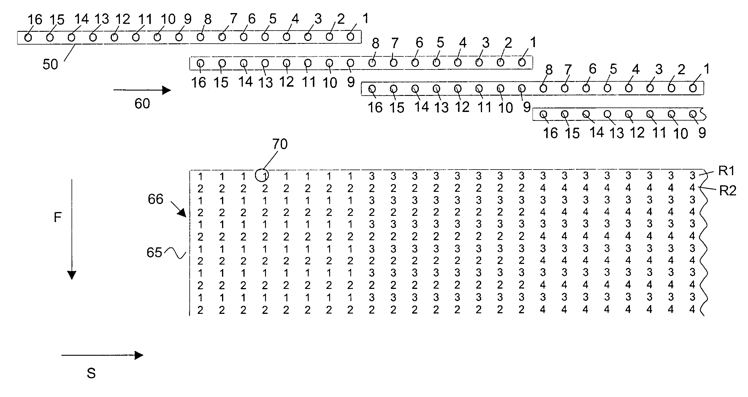
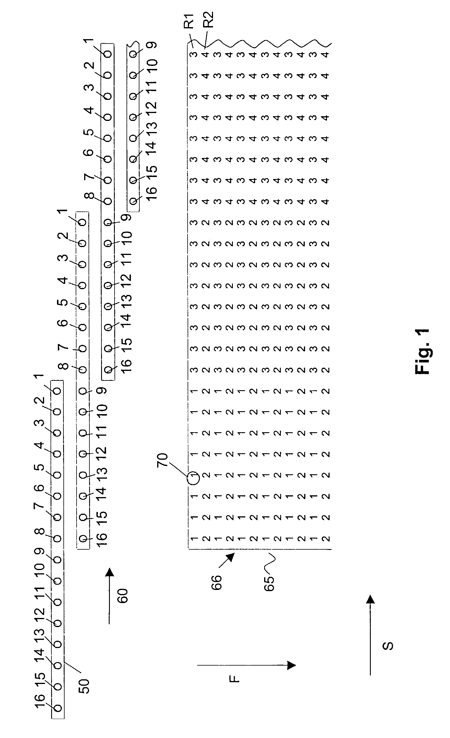
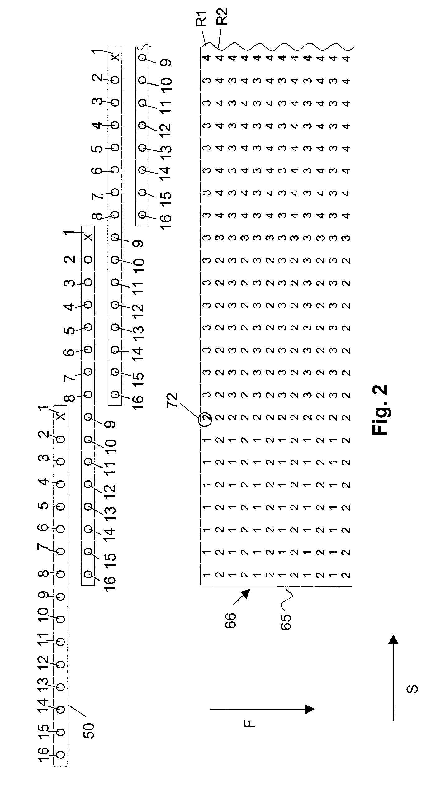
[0054] illustrated in FIG. 4A, the print head 50 is reconfigured by making two marking elements inactive at a first side A of the print head 50. The number of marking elements made inactive when reconfiguring the print head 50 equals the number of redundant marking elements in a set, which is two for the example under consideration. In the present case, 14 marking elements 1′–14′ remain active. The same redundancy as before reconfiguration of the print head 50 is kept (i.e. 2), so the 14 marking elements 1′–14′ are now divided into groups of 7. Redundant pairs of marking elements now become (1′, 8′), (2′, 9′), (3′, 10′), (4′, 11′), (5′, 12′), (6′, 13′) and (7′, 14′). It can be seen that every pixel position can be reached by two different marking elements, which are different from the two equivalent marking elements which could reach that pixel position before reconfiguration of the print head 50. If one of the marking elements is defect, the corresponding equivalent marking element...

second embodiment

[0056] or reconfiguration of the print head 50, illustrated in FIG. 4B, the print head 50 is reconfigured by making two marking elements inactive at a second side B of the print head 50. The number of marking elements made inactive when reconfiguring the print head 50 equals the number of redundant marking elements in a set, which is two for the example under consideration. In the present case, 14 marking elements 1′–14′ remain active. The same redundancy as before reconfiguration of the print head 50 is kept (i.e. 2), so the 14 marking elements 1′–14′ are now divided into groups of 7. Redundant pairs of marking elements now become (1′, 8′), (2′, 9′), (3′, 10′), (4′, 11′), (5′, 12′), (6′, 13′) and (7′, 14′). It can be seen that every pixel position can be reached by two different marking elements, which are different from the two equivalent marking elements which could reach that pixel position before reconfiguration of the print head 50. If one of the marking elements is defect, th...

third embodiment

[0058] which is a special case that can only be carried out if the defect marking elements are at the beginning or end of each of the redundant groups of marking elements, the print head 50 is reconfigured by keeping the non-defect marking elements as active marking elements, and making the defective marking elements at the beginning or end of each of the redundant groups inactive. When reconfiguring the print head 50, the active marking elements 1′–14′ are divided into redundant groups, while keeping the same redundancy as before reconfiguration of the print head 50. For the example under consideration, this means that the 14 active marking elements 1′–14′ are now divided into two groups of 7 active marking elements. Every active marking element 1′–14′ again has a redundant marking element. Redundant pairs of marking elements now become (1′, 14′), (2′, 8′), (3′, 9′), (4′, 10′), (5′, 11′), (6′, 12′), (7′, 13′). Again every pixel position can be reached by two different marking eleme...


PUM


Abstract

A dot matrix printer and printing method for being able to print a dot matrix on a printing medium using a plurality of marking elements on a printing head is described. A set of combinations of firing order of the plurality of marking elements is determined as well as a sequence of relative translation movements between the printing medium and the printing head so that all the dots in the dot matrix can be printed by application of each of the set of combinations, and any dot in the dot matrix can be printed by at least a first and a second equivalent marking element from a set of equivalent marking elements. For printing sets of dots in the dot matrix, a first equivalent marking element is selected from the set of equivalent marking elements to print the set of dots as part of a first firing order. If a pre-set number of equivalent marking elements of the set of equivalent marking elements are defective, the printing head is reconfigured so that other sets of at least first and second equivalent marking elements are determined.

Description

[0001]The application claims the priority of provisional U.S. patent application No. 60 / 368,312 filed Mar. 28, 2002.FIELD OF THE INVENTION[0002]The present invention relates to a method and an apparatus for printing, such as ink jet or thermal transfer printing, especially non-contact printing as well as to a control unit suitable for controlling such a printer.BACKGROUND OF THE INVENTION[0003]Printing is one of the most popular ways of conveying information to members of the general public. Digital printing using dot matrix is printers allows rapid printing of text and graphics stored on computing devices such as personal computers. These printing methods allow rapid conversion of ideas and concepts to a printed product at an economic price without time consuming and specialised production of intermediate printing plates such as lithographic plates. The development of digital printing methods has made printing an economic reality for the average person even in the home environment....

Claims


Application Information

Patent Timeline
Patent Type & Authority Patents(United States)
IPC IPC(8): B41J29/38B41J29/393B41J2/165B41J2/21
CPCB41J2/2139B41J2/2135
Inventor VANHOOYDONCK, RUDIBERGEN, PATRICK VAN DEN
Owner AGFA GEVAERT AG
Features
  • Generate Ideas
  • Intellectual Property
  • Life Sciences
  • Materials
  • Tech Scout
  • Unparalleled Data Quality
  • Higher Quality Content
  • 60% Fewer Hallucinations
Learn More