Dot-sequential color display system

a color display system and dot-sequential technology, applied in the field of dot-sequential color display systems, can solve the problems of potential 30% efficiency, further reduced to around 30% light utilization efficiency, etc., and achieve the effect of high resolution and economic method of displacing the image in tim

Inactive Publication Date: 2006-09-26
3M INNOVATIVE PROPERTIES CO
View PDF47 Cites 49 Cited by
  • Summary
  • Abstract
  • Description
  • Claims
  • Application Information

AI Technical Summary

Benefits of technology

[0011]First we create a color display, with one-third the resolution, e.g. 300 (×3)×600 full-color dots and then “sequentially”, on a field by field basis, we displace these 900 dots left and right (for instance) so that R, G and B overlap in space to create a 900 full-color dot image. In conventional display applications, such as electronic (e.g., LCD) display projectors, the pixellated display will have a resolution that corresponds to the desired final overall display resolution (e.g., 640×480, 800×600, 1024×768, 2048×1536, etc,) Dot-sequential Color uses a single LCD (or DMD, etc.) imaging device at the desired final resolution, but creates 3 slightly displaced images over time, to make the equivalent of a full-color image with very low cost. We therefore exploit the ability of the human eye to synthesize three displaced color images into an equivalent higher resolution color image. Such a displacement may also be called “dithering” or “dot dither”.
[0016]The preferred method of shifting the image of our device uses a simple tilted plate with a piezoelectric actuator. Another means of obtaining such a small image displacement uses a double-birefringence crystal and liquid crystal retarder which is switched between two polarization states to make a “solid state” and reliable and fast-switching displacement control device.
[0019]Our chromatic separation also preferably uses a holographic grating, but as a compensating dispersion, and not as a microlens. We propose a better solution to putting RG and B wavelengths into spatially distinct pixel regions (RGB subpixels) and we furthermore propose a more economical method of displacing the image in time. Our display system and method provides high-efficiency illumination and a high-resolution image to the human eye.

Problems solved by technology

The major drawback of this type of display is that one-third of the light emanating from the display (in the case of a single-chip DMD, transmitted through the color wheel and reflected off of the micromirror elements) is used at any one time, and due to a “dead-band” required between the color segments (to prevent any color cross-talk) this may be further reduced to around 30% light utilization efficiency.
Whereas all displays appear to be improved with increased brightness, this potential 30% efficiency is a serious detriment.

Method used


Image

  • Dot-sequential color display system
  • Dot-sequential color display system
  • Dot-sequential color display system

Examples


Embodiment Construction

[0044]The present invention relates to pixelated electronic (e.g., liquid crystal display, digital micromirror device, etc.) projection displays, sometimes referred to as electronic display projectors. The invention includes a dot sequential color display system that may be used in such an electronic display projector. It will be appreciated, however, that the dot sequential color display system of the present invention could alternatively be used in other display applications.

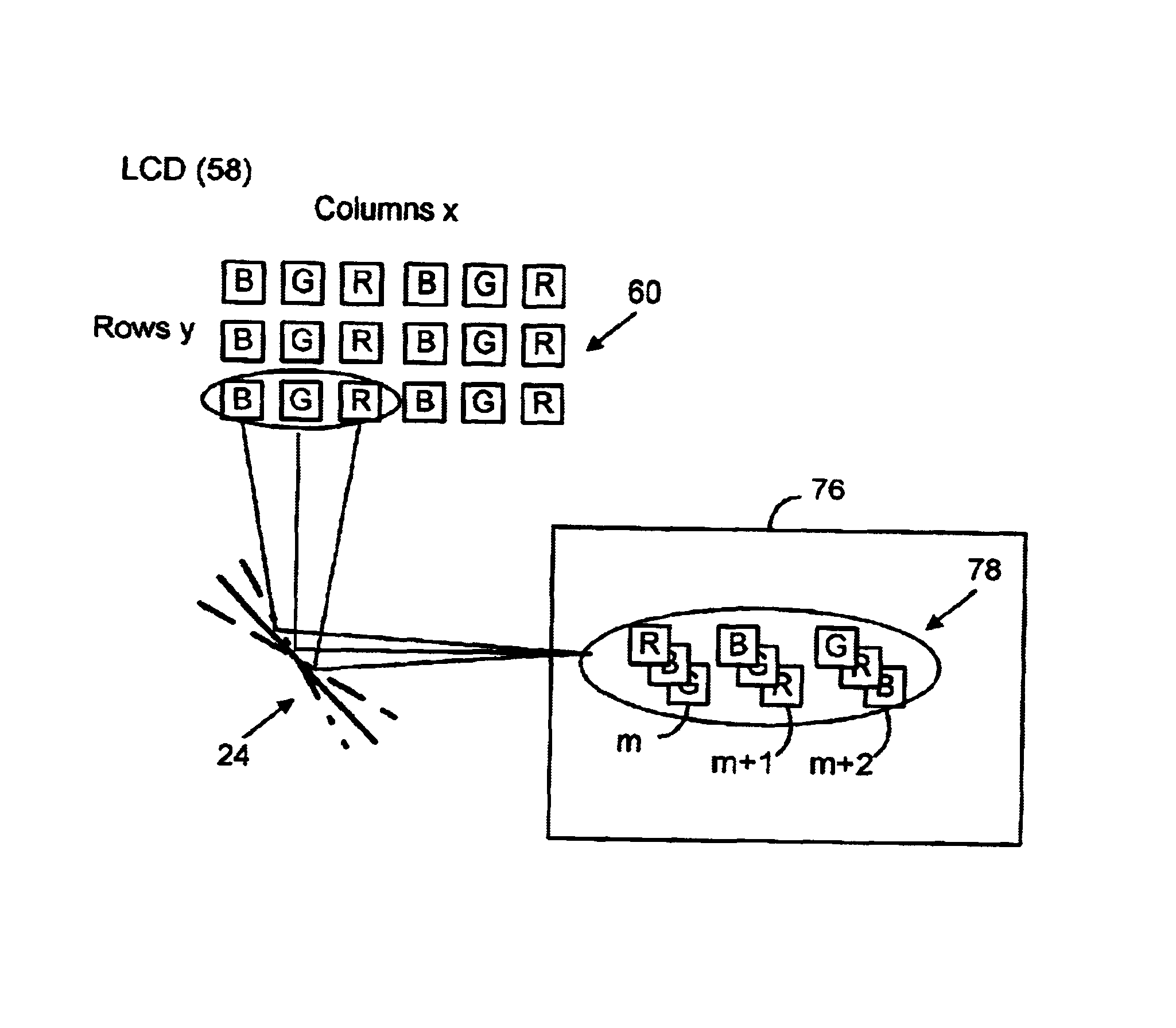
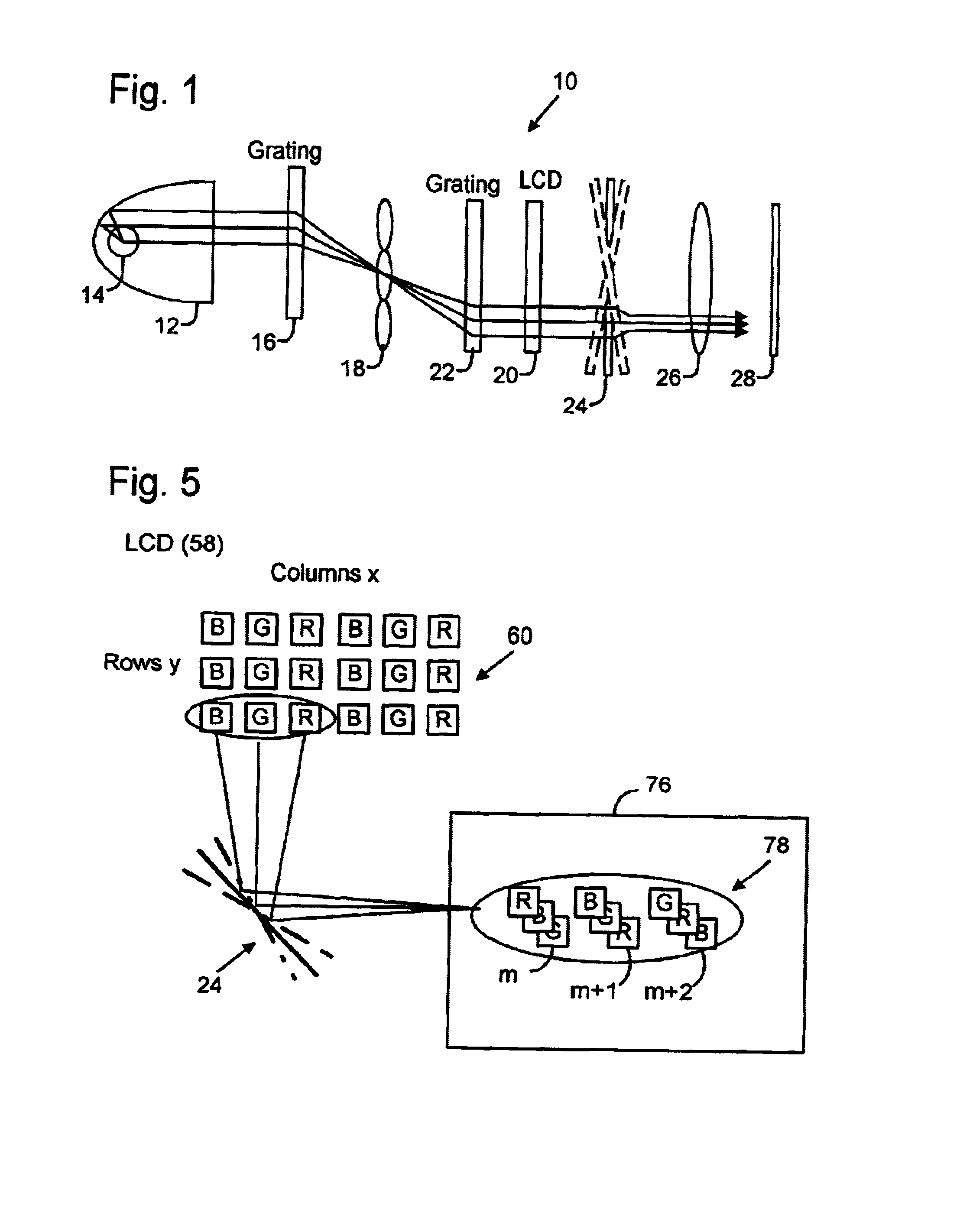
[0045]FIG. 1 is an optical schematic illustration of a dot sequential color display system 10 according to the present invention. A parabolic reflector 12 collects generally white light from a lamp 14 (e.g., an arc lamp) and directs the light in generally parallel rays to a first grating 16. Grating 16 disperses or separates color components of the light (e.g., red, green and blue “RGB”) and directs them to a microlens array 18 that focuses the dispersed light onto or toward a pixelated electronic display (e.g...


PUM

PropertyMeasurementUnit
wavelengthaaaaaaaaaa
thicknessaaaaaaaaaa
wavelengthaaaaaaaaaa

Abstract

1266-03028 A color display system includes a color light separator that separates incident white illumination light into red, green and blue wavelength bands to be directed to distinct color component sub-pixels (sometimes called dots) that are arranged in a dot-matrix, color triad arrangement (e.g., stripe or delta) to form individual picture elements (pixels) on a pixelated electronic image device (e.g., LCD of DMD). The entire picture is optically shifted from one set of color component sub-pixels to another in a 3-field sequence. As a result, the sets of red, green and blue color component sub-pixels appear to an observer as a single full-color image, thereby providing a dot sequential color display.

Description

SUMMARY OF INVENTION[0001]There are many ways to produce a full color matrix-addressed display, but almost all methods require 3 independent elements of Red, Green and Blue coloration, so as to be able to mix (in the additive color method) each primary in variable ratios to be able to cover the entire color gamut.[0002]One method that does not need 3 simultaneous primary color elements is referred to as field-sequential color. In this method an imaging device is illuminated with just one color primary at a time. One can envision a color-wheel that filters the white light and allows passage of first red, then green, then blue light, to be directed onto the imager, and if the sequencing is fast enough the human eye will integrate these R, G, B subimages into one full color image. In the early days of television it was proposed to use field-color sequential display, with a rotating color wheel in front of a white (broadband) emissive display (e.g. CRT) and cycle between red, green, and...

Claims


Application Information

Patent Timeline
Patent Type & Authority Patents(United States)
IPC IPC(8): G02F1/1335G02B26/08G03B21/00G03B21/14H04N9/12G02B27/10G02F1/13357H04N9/31
CPCG02B26/0875G02B27/1013G02B27/1046G02B27/1053G02B27/1066G02B27/1086H04N9/3197G02B27/148G02B27/149G02F1/133621H04N9/3111H04N9/3188G02B27/145G02F2001/133623G02F1/133623
Inventor CONNER, ARLIE R.CANNON, BRUCE L.ASPNES, ERIC
Owner 3M INNOVATIVE PROPERTIES CO
Why Eureka
Try Eureka