Liquid ejection head

a technology of liquid droplets and ejection ports, which is applied in the field of liquid droplets ejection heads, can solve the problems of difficult to obtain a sufficient effect, and achieve the effects of excellent growth, suppressing the volume of liquid droplets ejecting from the ejection port, and improving the ejecting speed of liquid droplets

Inactive Publication Date: 2006-05-02
CANON KK
View PDF22 Cites 25 Cited by
  • Summary
  • Abstract
  • Description
  • Claims
  • Application Information

AI Technical Summary

Benefits of technology

[0017]Accordingly, an object of the present invention is to provide a liquid ejection head capable of increasing the ejection speed of liquid droplets, stabilizing the amount (volume) of ejected liquid droplets, and simultaneously improving the ejection efficiency and the refill efficiency of the liquid.
[0018]Note that it is difficult to obtain a sufficient effect for the above object by the adjustment of a nozzle length because the nozzle length is variously restricted from the view point of a substrate size and a stroke. Thus, it is advantageous to adjust the sectional area of the nozzle. The extent to which the nozzle width can be adjusted is limited by the recent requirement for disposing electro-thermal transducers at a high density. In such circumstances, the inventors have focused attention on the fact that variation in the height of a nozzle greatly contributes to the improvement of ejection characteristics and refill characteristics.
[0019]To achieve the object described above, a liquid ejection head of the present invention has a plurality of ejection energy generation elements for generating energy for ejecting liquid droplets, an element substrate on which the plurality of energy generating elements are disposed, and a nozzle forming member laminated on the main surface of the element substrate and including (1) a plurality of nozzles each having an ejection port for ejecting liquid droplets, a bubble forming chamber in which bubbles are formed by an ejection energy generation element, and a supply path for supplying a liquid to the bubble forming chamber, and (2) a supply chamber for supplying the liquid to the plurality of nozzles, wherein the nozzle forming member has a protrusion, which reduces the height of each nozzle with respect to the main surface of the element substrate in the nozzle, in the vicinity of each ejection energy generation element on the supply path side thereof, and the height of the nozzle changes from the protrusion toward the supply chamber.
[0020]The liquid ejection head arranged as described above has a portion where the height of each nozzle is reduced and which is located in the gate electrode vicinity of each ejecting energy generation element on the supply path side thereof, and the height of the nozzle is changed toward the supply chamber, whereby when liquid droplets are ejected, the liquid having filled each bubble forming chamber is suppressed from being pushed out to a supply path by the bubbles generated in the bubble forming chamber. Thus, according to the liquid ejection head, fluctuation in the volume of the liquid droplets ejected from the ejection port can be suppressed, whereby the ejected volume of the liquid droplets can be properly stabilized. Further, according to the liquid ejection head, when a liquid droplet is ejected, it can be suppressed that the bubbles grown in the bubble forming chamber lose the pressure thereof by being abutted against the inner walls of the bubble forming chamber. Thus, according to the liquid ejection head, the ejecting speed of a liquid droplet can be improved because the bubbles in the bubble forming chamber can be excellently grown and the pressure thereof can be sufficiently stabilized.

Problems solved by technology

Note that it is difficult to obtain a sufficient effect for the above object by the adjustment of a nozzle length because the nozzle length is variously restricted from the view point of a substrate size and a stroke.

Method used


Image

  • Liquid ejection head
  • Liquid ejection head
  • Liquid ejection head

Examples


first embodiment

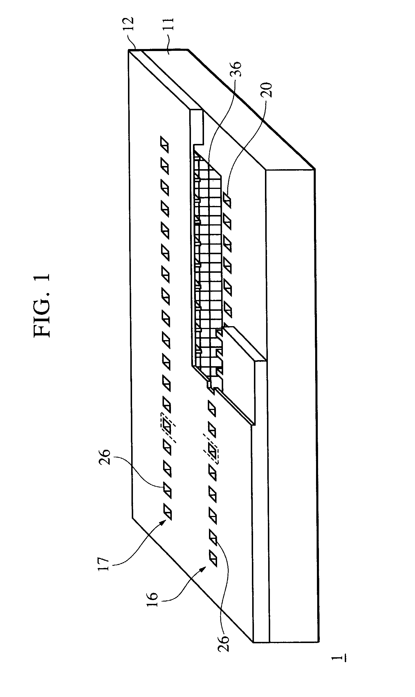
[0049]As shown in FIG. 1, a recording head 1 of a first embodiment is arranged such that a partition wall, which independently forms a nozzle acting as an ink flow path for each of a plurality of heaters acting as heating resistance elements, is extended from an ejection port to the vicinity of a supply port. This arrangement will be described later. The recording head 1 has an ink ejection unit to which the inkjet recording method disclosed in Japanese Patent Laid-Open Nos. 4-10940 and 4-10941 is applied, and bubbles generated when ink is ejected are communicated with outside air through the ejection ports.

[0050]Then, the recording head 1 includes a first nozzle train 16, which has a plurality of heaters and a plurality of nozzles with the respective nozzles arranged parallel to each other in the long direction thereof, and a second nozzle train 17 disposed at a position confronting the first nozzle train 16 across supply ports. The respective adjacent nozzles of the first and seco...

second embodiment

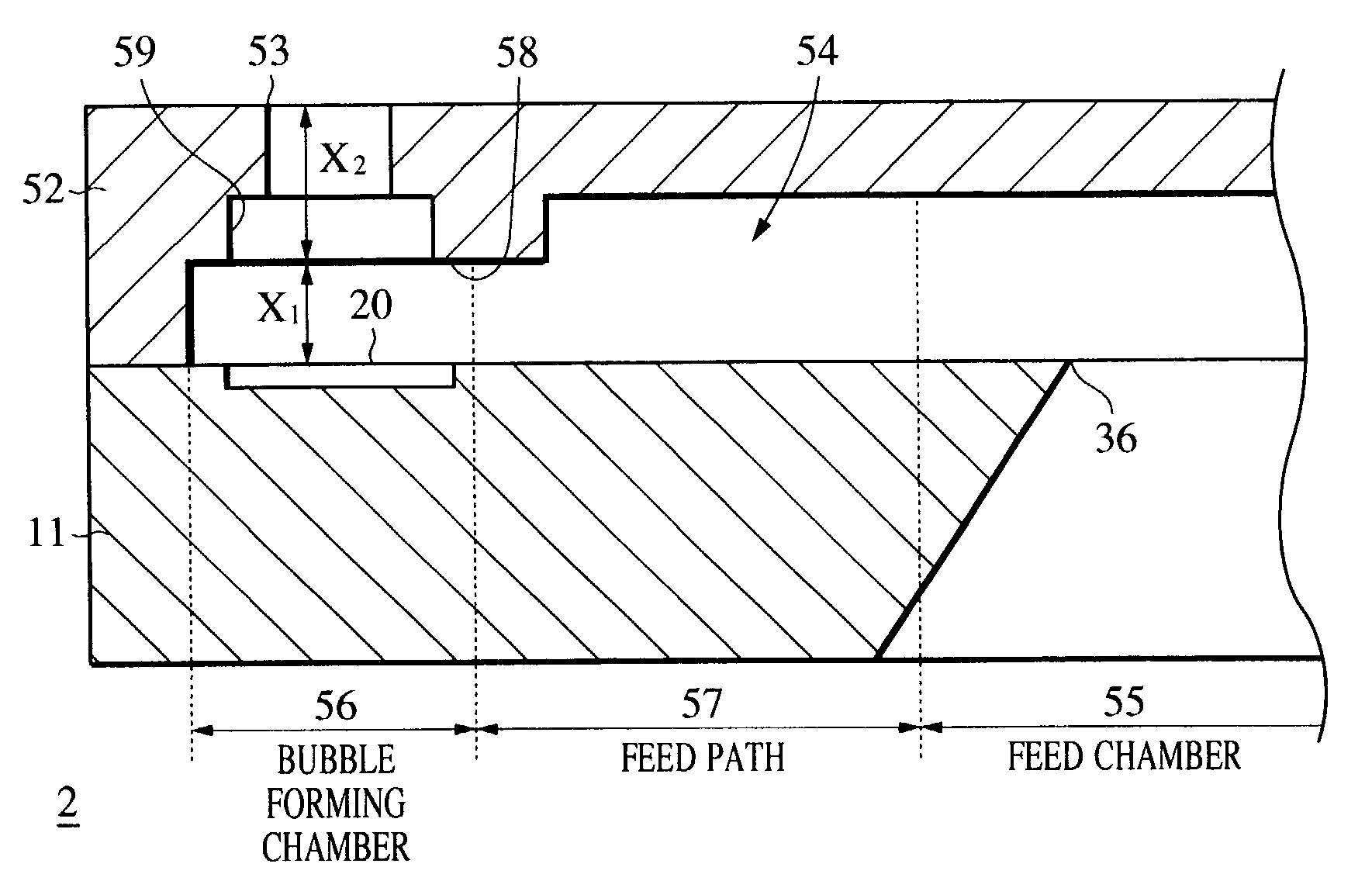
[0103]The recording head 1 described above is provided with the control sections 33 for preventing the ink having filled the bubble forming chamber 31 from flowing into the supply paths 32. A second embodiment will describe a recording head 2 having control sections for controlling bubbles, which grow in bubble forming chambers 31, and for controlling the flow of ink flowed by the bubbles. Note that, in the recording head 2, the same components as those used in the recording head 1 described above are denoted by the same reference numerals, and the description thereof is omitted.

[0104]As shown in FIG. 11, a nozzle forming member 52 provided with the recording head 2 is formed of a resin material to a thickness of about 30 μm. As shown in FIG. 12, the nozzle forming member 52 includes a plurality of ejection ports 53 for ejecting ink droplets, a plurality of nozzles 54 through which ink flows, and a supply chamber 55 for supplying ink to the respective nozzles 54.

[0105]The ejection p...

third embodiment

[0120]A recording head 3 of a third embodiment in which the height of first control sections 58 of the recording head 2 is more reduced will be briefly described with reference to the drawings. Note that, in the recording head 3, the same components as those of the recording heads 1 and 2 described above are denoted by the same reference numerals, and the description thereof is omitted.

[0121]As shown in FIG. 14, a nozzle forming member 62 provided with the recording head 3 is formed of a resin material to a thickness of about 30 μm. The nozzle forming member 62 includes a plurality of ejection ports 63 for ejecting ink droplets, a plurality of nozzles 64 through which ink flows, and a supply chamber 65 for supplying ink to the respective nozzles 64.

[0122]The ejection ports 63 are formed at positions where they confront heaters 20 on an element substrate 11 and arranged as circular holes each having a diameter of, for example, about 15 μm. Note that the ejection ports 63 may be forme...


PUM


Abstract

A liquid ejection head has an element substrate on which a plurality of heaters for generating energy for ejecting liquid droplets are disposed, a nozzle forming member laminated on the main surface of the element substrate and including a plurality of nozzles each having an ejection port for ejecting liquid droplets, a bubble forming chamber in which bubbles are formed by a heater, and a supply path for supplying liquid from a supply chamber to the bubble forming chamber. The nozzle forming member has a portion located in the vicinity of the heaters on the supply path side where the height of the nozzles is reduced, whereby the height of the nozzles changes toward the supply chamber.

Description

BACKGROUND OF THE INVENTION[0001]1. Field of the Invention[0002]The present invention relates to a liquid ejection head for executing recording on a recording medium by ejecting liquid droplets such as, for example, ink droplets, and more particularly, to a liquid ejection head for executing inkjet recording.[0003]2. Description of the Related Art[0004]An inkjet recording system is one of so-called non-impact recording systems.[0005]This inkjet recording system produces a negligible degree of small noise in recording and can execute recording at a high speed.[0006]Further, the inkjet recording system can execute recording on various types of recording mediums, that is, it can fix ink on so-called plain paper without the need of special processing, and further can obtain a very fine image at a low cost. Recently, the inkjet recording system has become widely used rapidly as a recording means for a copier, facsimile, word processor, and the like due to these advantages, in addition to...

Claims


Application Information

Patent Timeline
Patent Type & Authority Patents(United States)
IPC IPC(8): B41J2/14B41J2/16B41J2/05
CPCB41J2/1404B41J2/1603B41J2/1629B41J2/1637B41J2/1645B41J2/1631B41J2002/14475B41J2002/14403B41J2002/14169
Inventor KUBOTA, MASAHIKOMIYAGAWA, MASASHI
Owner CANON KK
Why Eureka
Try Eureka