Fluid ejection device

a technology of fluid ejection and ejection device, which is applied in printing and other directions, can solve the problems of inability to control the ejection force of ink, inability to uniformly or uniformly eject ink, and inability to achieve uniformity or ink residuals, so as to reduce the size of the fluid ejection device and enhance the fluid ejection speed

Active Publication Date: 2007-07-31
MACRONIX INT CO LTD
View PDF2 Cites 5 Cited by
  • Summary
  • Abstract
  • Description
  • Claims
  • Application Information

AI Technical Summary

Benefits of technology

[0010]Accordingly, the present invention is directed to a fluid ejection device, adapted for ejecting the fluid at a nano-second level speed and to precisely control the quantity of the fluid ejected thereby. The fluid ejection device is suitable for an ink-jet printer.
[0011]The present invention is also directed to a method of fabricating a fluid ejection device. The fabrication method is capable of further reducing the size of the fluid ejection device.
[0012]The present invention is also directed to a method of operating a fluid ejection device, which is capable of enhancing the fluid ejection speed and precisely controlling the quantity of the fluid rejected thereby.
[0016]According to an embodiment of the present invention, a micro-electromechanical structure is used for fluid ejection, and therefore the fluid ejection speed can be at a nano-second level and the fluid quantity ejected thereby can be precisely controlled. Moreover, according to an embodiment of the present invention, the micro-electromechanical technology is applied for fabricating the fluid ejection device, and therefore the size of the fluid ejection device can be effectively reduced and can be adapted for meeting the high resolution requirement of ink-jet printers. Additionally, a voltage is applied for controlling the fluid ejection instead of using a heater, and therefore damage attributed to the high temperature can be effectively avoided.

Problems solved by technology

The disadvantage is that the ink is easily ejected due to pressure and the ejection force of the ink cannot be controlled.
The ink is adversely affected by law of inertia at the nozzle, resulting in non-uniformity or ink residuals.
The other disadvantage is that, because the ink-jet head of the bubble ink-jet technology is usually under high temperature situation due to use of heater, and therefore the ink-jet head is easily damaged, especially in absence of ink therein.
The problem is that it is not possible to further reduce the quantity of ejected ink.

Method used


Image

  • Fluid ejection device
  • Fluid ejection device
  • Fluid ejection device

Examples


Embodiment Construction

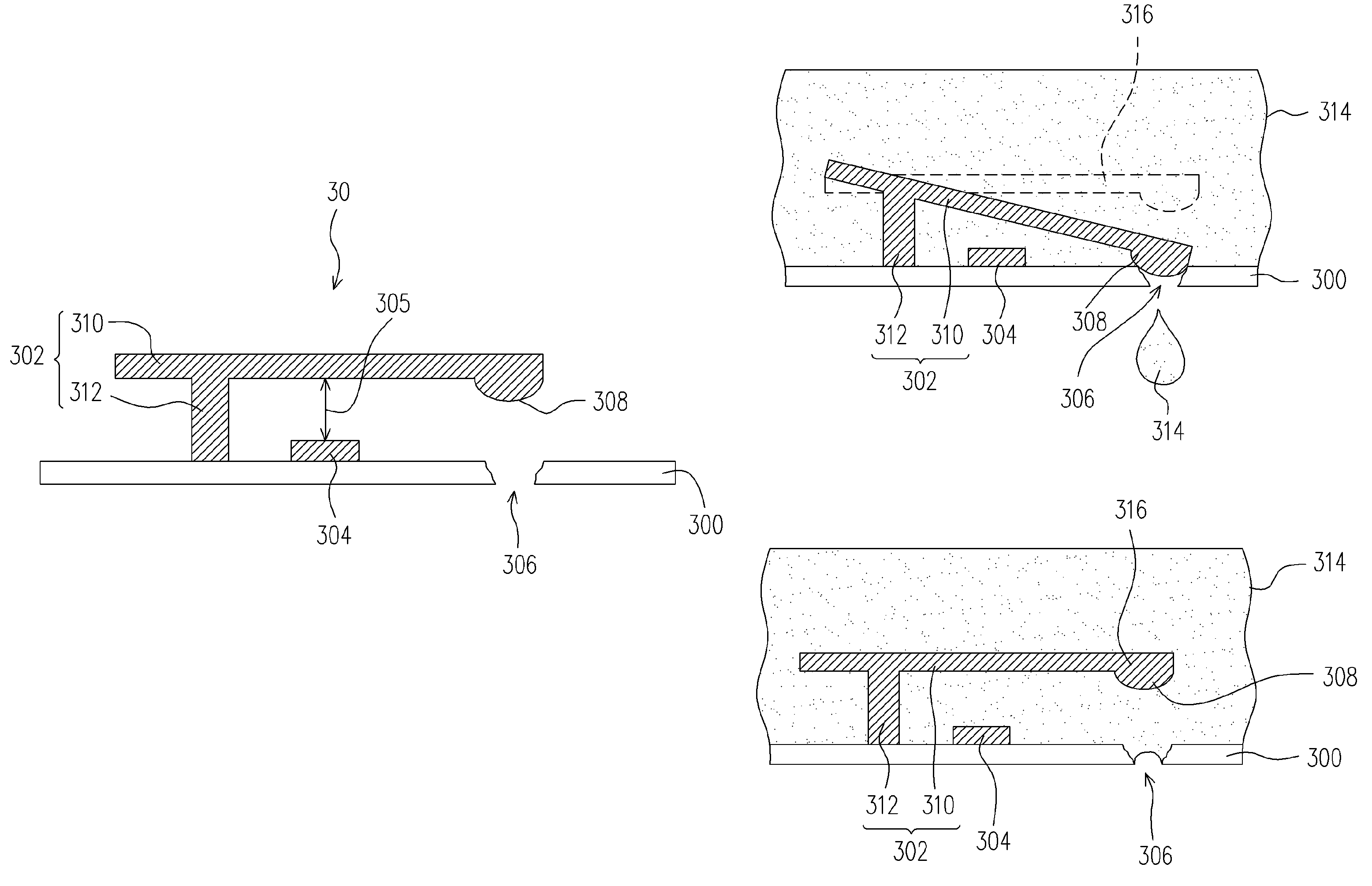
[0023]FIG. 3A is a cross-sectional view showing a fluid ejection device according to an embodiment of the present invention. FIGS. 3B and 3C are schematic drawings showing a method of operating the fluid ejection device of FIG. 3A according to an embodiment of the present invention.

[0024]Please referring to FIG. 3A, the exemplary fluid ejection device 30 comprises: a substrate 300, a beam 302 and an activation pad 304. The substrate 300 comprises an orifice 306 formed thereon. The beam 302 comprises a fixed portion 312 and a cantilever portion 310, wherein the cantilever portion 310 is disposed over and correspond to the orifice 306. The activation pad 304 is disposed between the cantilever portion 310 of the beam 302 and the substrate 300.

[0025]In an embodiment of the present invention, the fixed portion 312 is, for example, a pillar structure formed on the substrate 300 and is adapted for supporting the cantilever portion 310. The activation pad 304 on the substrate 300 is separat...


PUM


Abstract

A fluid ejection device, a method and an operation method thereof are disclosed. The fluid ejection device includes a substrate, a beam and an activation pad. The substrate has an orifice, and the beam includes a fixed portion and a cantilever portion and is disposed over the substrate, wherein the cantilever portion is disposed over the orifice. Furthermore, the activation pad is disposed between the cantilever portion of the beam and the substrate. Because the fluid ejection device of the present invention is fabricated by using micro-electromechanical technology, and therefore it possible to obtain a fluid ejection device capable of ejecting the fluid from the orifice at a high-speed and also the quantity fluid ejected can be very small.

Description

BACKGROUND OF INVENTION[0001]1. Field of the Invention[0002]The present invention relates to a fluid ejection device, a fabrication method and an operating method thereof, adapted for an ink-jet printing head; and more particularly to a micro-electromechanical system (MEMS) fluid ejection device, a fabrication method and an operating method thereof.[0003]2. Description of Related Art[0004]To date, the ink-jet technology includes the bubble ink-jet technology and the piezoelectric ink-jet technology.[0005]FIGS. 1A and 1B are schematic drawings showing an ink-jet head and an operation of the prior art bubble ink-jet technology. Referring to FIG. 1A, in the ink-jet head 100 adopted by the prior art bubble technology, the ink 104 is heated by a heater 102 for generating the bubble 106. Thereafter, the ink 104 is ejected from a nozzle 108 under the pressure of the bubble 106.[0006]Referring to FIG. 1B, when the heater 102 stops heating, the bubble 106 in the ink 104 will not be inflated ...

Claims


Application Information

Patent Timeline
Patent Type & Authority Patents(United States)
IPC IPC(8): B41J2/04B41J2/05B41J2/14
CPCB41J2/14427
Inventor WONG, DANIEL MAN-TUNGKU, YEN-HUI
Owner MACRONIX INT CO LTD
Why Eureka
Try Eureka