Liquid ejection head
a liquid ejection and head technology, applied in printing and other directions, can solve the problems of difficult to obtain a sufficient effect, and achieve the effect of increasing the ejection speed of liquid droplets, improving the ejection efficiency and the refill efficiency of liquid, and stabilizing the amount (volume) of liquid droplets
- Summary
- Abstract
- Description
- Claims
- Application Information
AI Technical Summary
Benefits of technology
Problems solved by technology
Method used
Image
Examples
first embodiment
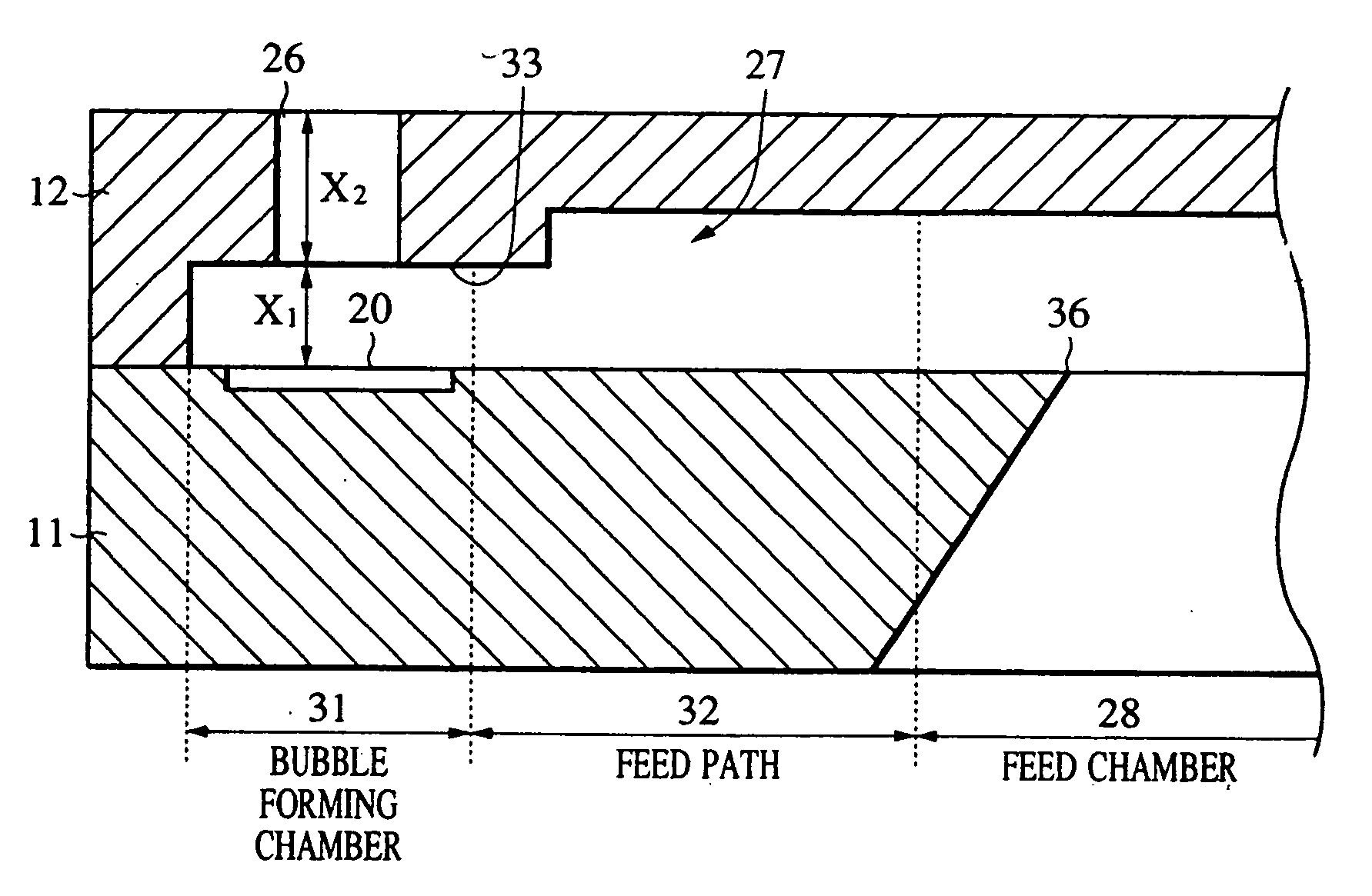
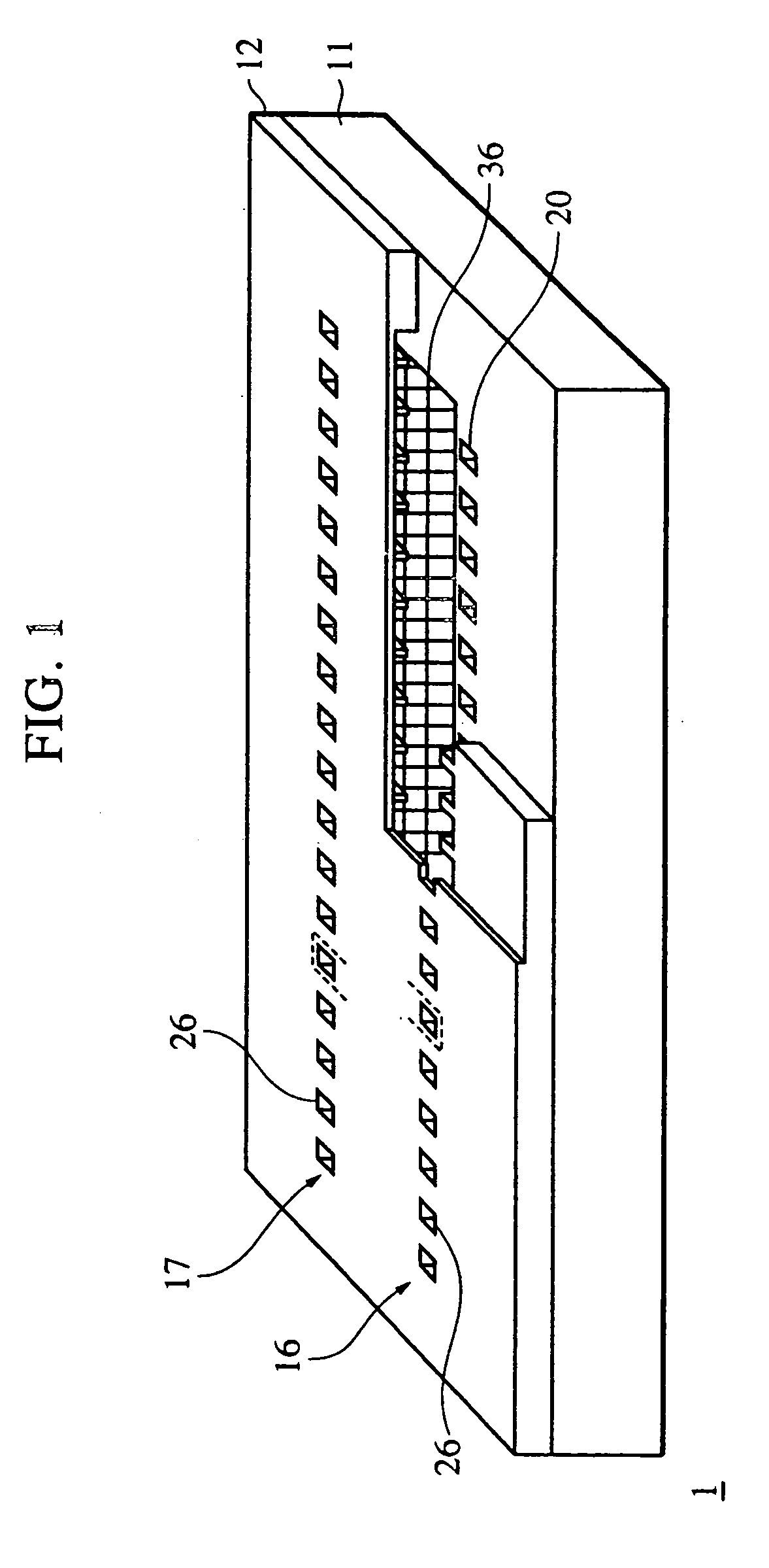
[0050] As shown in FIG. 1, a recording head 1 of a first embodiment is arranged such that a partition wall, which independently forms a nozzle acting as an ink flow path for each of a plurality of heaters acting as heating resistance elements, is extended from an ejection port to the vicinity of a supply port. This arrangement will be described later. The recording head 1 has an ink ejection unit to which the inkjet recording method disclosed in Japanese Patent Laid-Open Nos. 4-10940 and 4-10941 is applied, and bubbles generated when ink is ejected are communicated with outside air through the ejection ports.
[0051] Then, the recording head 1 includes a first nozzle train 16, which has a plurality of heaters and a plurality of nozzles with the respective nozzles arranged parallel to each other in the long direction thereof, and a second nozzle train 17 disposed at a position confronting the first nozzle train 16 across supply ports. The respective adjacent nozzles of the first and s...
second embodiment
[0104] The recording head 1 described above is provided with the control sections 33 for preventing the ink having filled the bubble forming chamber 31 from flowing into the supply paths 32. A second embodiment will describe a recording head 2 having control sections for controlling bubbles, which grow in bubble forming chambers 31, and for controlling the flow of ink flowed by the bubbles. Note that, in the recording head 2, the same components as those used in the recording head 1 described above are denoted by the same reference numerals, and the description thereof is omitted.
[0105] As shown in FIG. 11, a nozzle forming member 52 provided with the recording head 2 is formed of a resin material to a thickness of about 30 μm. As shown in FIG. 12, the nozzle forming member 52 includes a plurality of ejection ports 53 for ejecting ink droplets, a plurality of nozzles 54 through which ink flows, and a supply chamber 55 for supplying ink to the respective nozzles 54.
[0106] The eject...
third embodiment
[0121] A recording head 3 of a third embodiment in which the height of first control sections 58 of the recording head 2 is more reduced will be briefly described with reference to the drawings. Note that, in the recording head 3, the same components as those of the recording heads 1 and 2 described above are denoted by the same reference numerals, and the description thereof is omitted.
[0122] As shown in FIG. 14, a nozzle forming member 62 provided with the recording head 3 is formed of a resin material to a thickness of about 30 μm. The nozzle forming member 62 includes a plurality of ejection ports 63 for ejecting ink droplets, a plurality of nozzles 64 through which ink flows, and a supply chamber 65 for supplying ink to the respective nozzles 64.
[0123] The ejection ports 63 are formed at positions where they confront heaters 20 on an element substrate 11 and arranged as circular holes each having a diameter of, for example, about 15 μm. Note that the ejection ports 63 may be ...
PUM
 Abstract
Description
Claims
Application Information
 - R&D
- Intellectual Property
- Life Sciences
- Materials
- Tech Scout
- Unparalleled Data Quality
- Higher Quality Content
- 60% Fewer Hallucinations
Browse by: Latest US Patents, China's latest patents, Technical Efficacy Thesaurus, Application Domain, Technology Topic, Popular Technical Reports.
© 2025 PatSnap. All rights reserved.Legal|Privacy policy|Modern Slavery Act Transparency Statement|Sitemap|About US| Contact US: help@patsnap.com


