Energy-saving heat dissipation type LED street lamp

A heat-dissipating technology for LED street lamps, applied in lighting and heating equipment, cooling/heating devices of lighting devices, lighting devices, etc., can solve the problems of small LED lamp packaging area, poor heat dissipation effect, and affecting the life of LED lamps. Achieve the effect of improving heat dissipation and cooling effect, good heat dissipation and cooling effect, and good heat dissipation effect

Active Publication Date: 2020-01-17
ZHANGZHOU HETAI ELECTRIC LIGHTING SOURCE TECH
View PDF4 Cites 6 Cited by
  • Summary
  • Abstract
  • Description
  • Claims
  • Application Information

AI Technical Summary

Problems solved by technology

[0002] LED street lamps are currently the most energy-saving and environmentally friendly lighting products used on various roads, but LED light sources have high requirements for heat dissipation, because LED lights convert part of the electrical energy into visible light, and other energy is converted into heat energy. Moreover, the package area of ​​the LED lamp is small, and the heat dissipation through convection and radiation is less. If the excess heat is not dissipated through the cooling system, a large amount of heat will accumulate in the LED lamp, which will affect the life of the LED lamp.
[0003] The heat dissipation of LED lamps in the prior art generally includes the following methods: first, through the natural convection between the surface of the lampshade of the LED street lamp and the air, the heat generated by the lamp body of the LED street lamp is dissipated, but since the lamp body is inside the lampshade, this The heat dissipation method is not good for the heat dissipation effect of the lamp body; secondly, a radiator or a cooling fan with a large cross-sectional area is installed on the LED lamp to assist heat dissipation, but because it is used in the street lamp industry, the lampshade of the street lamp is generally a large internal space. For small strips, it is obviously unrealistic to install radiators or cooling fans with large cross-sectional areas

Method used


Image

  • Energy-saving heat dissipation type LED street lamp
  • Energy-saving heat dissipation type LED street lamp
  • Energy-saving heat dissipation type LED street lamp

Examples


Embodiment 1

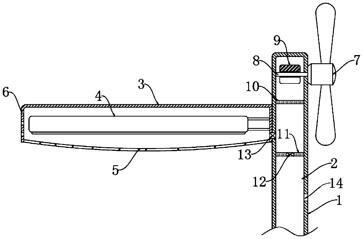
[0022] Reference figure 1 , An energy-saving and heat-dissipating LED street light, comprising a lamp pole 1 and a lamp shade 3 fixedly connected to the side wall of the lamp pole 1, the lower end of the lamp shade 3 is open and a transparent cover 5 is provided, and a lamp body 4 is fixedly installed on the inner wall of the lamp shade 3, The side walls of the lampshade 3 away from the light pole 1 are provided with heat dissipation holes 6, and a cavity 2 is opened in the side wall of the light pole 1, and an impeller 7 is rotatably connected to the side wall of the light pole 1 through a fixed shaft 8, and the fixed shaft 8 penetrates A magnetic block 9 is fixedly connected to the cavity 2.

[0023] The impeller 7 has three to five blades. The width of the blades is much larger than the width of the light pole 1, and there is a sufficient distance between the end of the blade close to the light pole 1 and the light pole 1, so the light pole 1 will not obstruct the rear of the i...

Embodiment 2

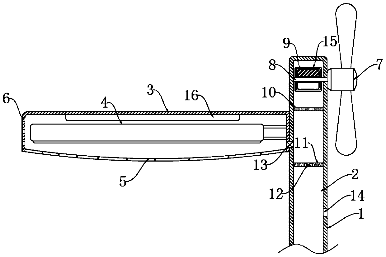
[0031] Reference figure 2 The difference from Embodiment 1 is that: the outer ring of the magnetic block 9 is provided with a multi-turn spiral coil 15 in a closed state, and the top of the lampshade 3 is fixedly connected with a battery 16 coupled with the spiral coil 15, the battery 16 and the lamp body 4 coupling.

[0032] When the impeller 7 is driven to rotate by the airflow, the magnetic block 9 is driven to rotate synchronously under the action of the fixed shaft 8, and the direction of the magnetic field of the magnetic block 9 is constantly changing, so the magnetic induction line of the magnetic block 9 and the spiral coil 15 are always in relative motion. The spiral coil 15 is equivalent to cutting the magnetic induction wire. According to the principle of electromagnetic induction, the spiral coil 15 will generate an induced current. The battery 16 is coupled with the spiral coil 15. The induced current generated on the spiral coil 15 can be stored in the battery 16, ...

Embodiment 3

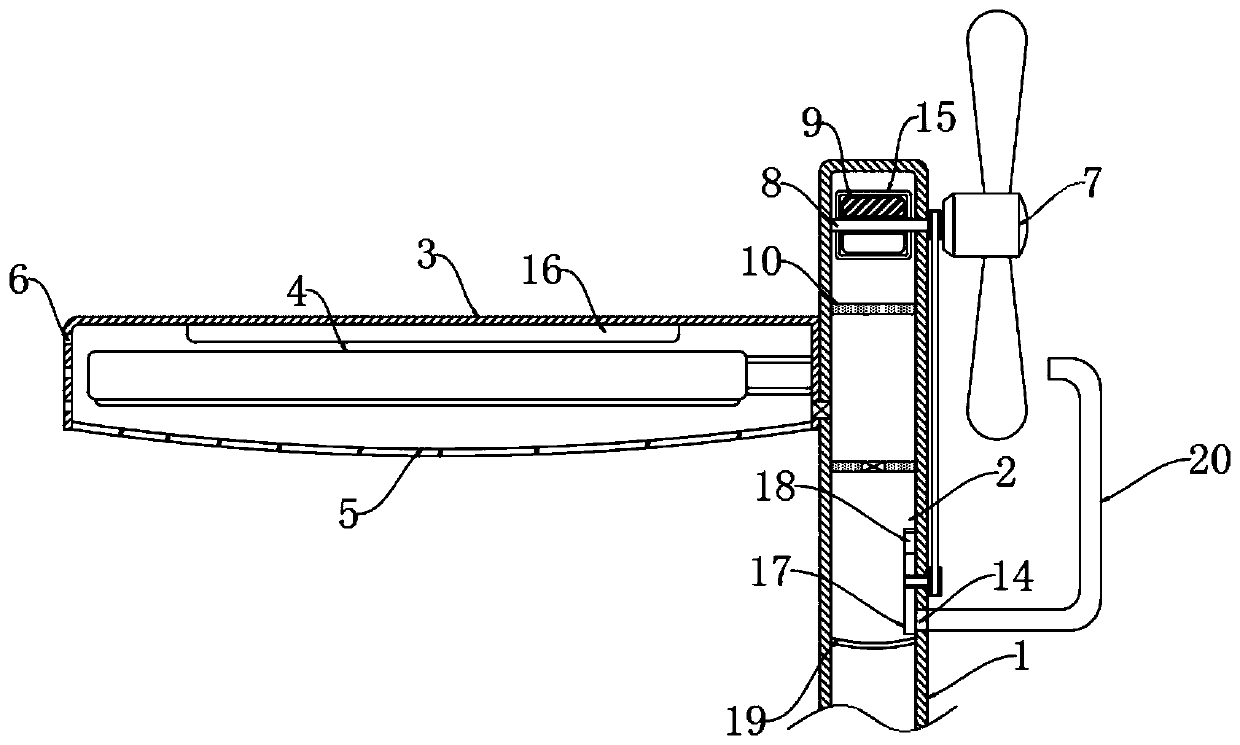
[0034] Reference image 3 The difference from Embodiment 2 is that the cavity 2 is sealed and fixedly connected with an elastic membrane 19 at a position below the air outlet 14, and the air outlet 14 is connected with a bent tube 20, and the outlet end of the bent tube 20 is located opposite to the impeller 7 The blades at the lower end and the air flow from the outlet end of the bent tube 20 can promote the rotation of the impeller 7. The cavity 2 is located on the inner wall between the fixed plate 11 and the elastic membrane 19 and is connected to the disc 17 through a rotating shaft. The disc 17 is provided with a through hole 18 that matches with the air outlet 14. The disc 17 has the air outlet in the initial state 14 is sealed, the rotating shaft penetrates to the outside of the light pole 1 and is connected to the fixed shaft 8 through a belt pulley.

[0035] It should be noted that the size of the pulley on the fixed shaft 8 is larger than the size of the pulley on the...


PUM


Abstract

The invention discloses an energy-saving heat dissipation type LED street lamp that comprises a lamp post and a lampshade fixedly connected to the side wall of the lamp post; the lower end of the lampshade is open and provided with a transparent cover, a lamp body is fixedly installed on the inner wall of the lampshade; heat dissipation holes are formed in the side wall, away from the lamp post, of the lampshade; a cavity is formed in the side wall of the lamp post, and an impeller is rotationally connected to the side wall of the lamp post through a fixing shaft. The impeller, a magnetic block, a movable plate and a fixed plate are arranged; the impeller can be driven to rotate by airflow, therefore, the movable plate slides up and down; hot air in the lampshade is pumped out, and external cold air enters the lampshade; therefore, a good heat dissipation and cooling effect on the street lamp is achieved, current can be generated and stored for supplying power to the street lamp, electric energy is saved, meanwhile, the pumped hot air can be used for promoting rotation of the impeller, cyclic utilization of energy is achieved, and the heat dissipation and cooling effect and the electric energy saving effect of the street lamp are further improved.

Description

Technical field [0001] The invention relates to the technical field of lamps, in particular to an energy-saving and heat-dissipating LED street lamp. Background technique [0002] LED street lights are currently the most energy-saving and environmentally friendly lighting products used on various roads, but LED light sources have high requirements for heat dissipation, because LED lights convert part of the electrical energy into visible light, and other energy is converted into heat. In addition, the LED lamp has a small packaging area and less heat dissipation through convection and radiation. If the excess heat is not dissipated through the heat dissipation system, a large amount of heat will be accumulated in the LED lamp, which will affect the life of the LED lamp. [0003] The heat dissipation of LED lamps in the prior art generally includes the following methods: First, the heat generated by the lamp body of the LED street lamp is dissipated through the natural convection be...

Claims


Application Information

Patent Timeline
Patent Type & Authority Applications(China)
IPC IPC(8): F21S9/02F21V29/60F21Y115/10F21W131/103
CPCF21S9/026F21W2131/103F21V29/60F21Y2115/10
Inventor 陈启转
Owner ZHANGZHOU HETAI ELECTRIC LIGHTING SOURCE TECH
Why Eureka
Try Eureka