
Cooperative communication method and equipment

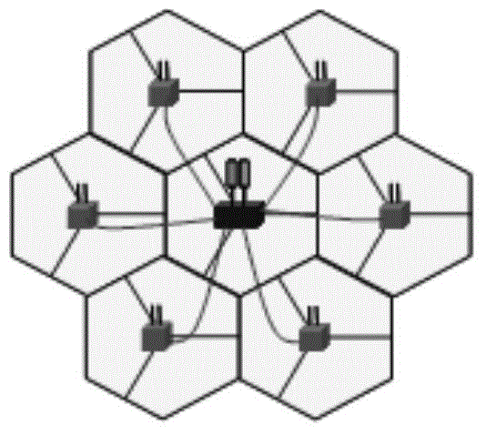
A technology of cooperative communication and communication mode, applied in the computer field, can solve the problems of large delay, poor cooperative communication performance, and the transmission conditions of the second base station are not as good as that of the first base station, etc., and achieves low delay, improved overall performance, and fast information exchange. Effect

Inactive Publication Date: 2015-07-29
HUAWEI TECH CO LTD
View PDF5 Cites 10 Cited by
  • Summary
  • Abstract
  • Description
  • Claims
  • Application Information

AI Technical Summary

Problems solved by technology

However, a prominent problem of Weak backhaul is that the delay between each other is relatively large, often around 20ms
For example: Considering DPS (Dynamic Point Selection, dynamic transmission point selection), if at time n, the primary serving first base station receives the CSI (Channel State Information, channel state information) reported by the UE, the CSI information reflects the first base station and the second The transmission quality of the wireless links between the base stations and the UE, so that the first base station judges that the transmission conditions of the second base station are better, so it decides that the second base station will perform data transmission, and then sends an instruction to the second base station through backhaul , instructing the second base station to provide transmission services to the UE, but because the indication information may take 20ms to reach the second base station, the second base station can only transmit downlink data after 20ms, and at this time, because 20ms has passed, the second base station The transmission conditions of the second base station may not be as good as the first base station
[0009] It can be seen that in the backhaul scenario with large delay, the performance of cooperative communication between base stations is poor

Method used


Image

  • Cooperative communication method and equipment
  • Cooperative communication method and equipment
  • Cooperative communication method and equipment

Examples


Embodiment Construction

[0073] In order to enable those skilled in the art to better understand the technical solutions in the embodiments of the present invention, and to make the above-mentioned purposes, features and advantages of the embodiments of the present invention more obvious and understandable, the following describes the technical solutions in the embodiments of the present invention in conjunction with the accompanying drawings For further detailed explanation.

[0074] First, a cooperative communication method provided by the present invention is introduced.

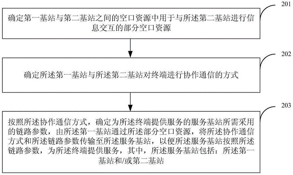
[0075] see figure 2 , is a flow of an embodiment of a cooperative communication method provided by the present invention, and the processing flow may specifically include:

[0076] Step 201. Determine a part of the air interface resources used for information interaction with the second base station among the air interface resources between the first base station and the second base station.

[0077] In the prior art, the air ...


PUM


Abstract

Embodiments of the present invention disclose a coordinated communication method and device. The method comprises: determining, among the air interface resources between a first base station and a second base station, the part of air interface resources that is used for information exchange with the second base station; determining the coordinated communication mode used by the first base station and the second base station to communicate with a terminal; determining, according to the coordinated communication mode, the link parameters needed for a serving base station to provide services to the terminal, and the first base station transmitting the coordinated communication mode and the link parameters to the serving base station via the part of the air interface so that the serving base station can provide services to the terminal according to the link parameters, the serving base station comprising the first base station and / or the second base station. The embodiments of the present invention enhance the comprehensive coordinated communication among base stations in scenarios having backhaul of large delays.

Description

technical field [0001] The present invention relates to the field of computer technology, in particular to a cooperative communication method and equipment. Background technique [0002] In general wireless communication systems, such as LTE (Long Term Evolution, long-term evolution) systems, the network coverage is divided into individual cells (Cells), and each cell is usually provided by a BS (Base Station, base station) Serve. This base station is called the serving base station of the cell. Each BS provides downlink transmission and uplink reception services to UEs (User Equipment, user equipment) in its cell. [0003] In a traditional wireless communication network, each base station maintains a relatively independent working mode, that is, each base station is only responsible for uplink and downlink scheduling for UEs in its own cell, and provides downlink transmission and uplink reception services. A base station typically neither assists nor interferes with how ...

Claims


Application Information

Patent Timeline
IPC IPC(8): H04L5/00H04W72/08H04W72/12
CPCH04L5/0023H04W72/12H04W72/542H04L5/0035H04B7/024H04B7/063H04B7/0632H04B7/0639
Inventor 李强杨晓东王学龙高永强高毓恺
Owner HUAWEI TECH CO LTD
Learn More