Apparatus, systems and methods for management of raw water and emissions utilizing heat and/or pressure energy within combustion gas sources

Inactive Publication Date: 2018-08-02
HORIZON OILFIELD SOLUTIONS
View PDF14 Cites 12 Cited by
  • Summary
  • Abstract
  • Description
  • Claims
  • Application Information

AI Technical Summary

Benefits of technology

[0048]In accordance with the invention, there is provided methods and apparatus to concentrate waste water contaminants. In a first aspect, the invention provides an adaptor for connecting an engine exhaust source from an associated engine to a raw water vaporization system (RWVS), the adaptor having an exhaust conduit having an engine exhaust connector for connecting the conduit to engine exhaust pipin

Problems solved by technology

While larger particles are generally easily removed, finer particles can become increasingly problematic within the concentrating solutions as viscosity increases and increasingly larger particles may become suspended in the solution and can lead to scaling and/or plugging of lines.
In other words, heretofore there has been no incentive for mobile treatment of flue gasses on remote or stranded drilling sites because there are local and national exemptions to standard air emission regulations on oil and gas drilling sites related to diesel engine exhaust volume and concentration of discharge within relatively short timeframes.
The byproduct of the combustion heat utilized by these systems is a low grade heat that is no longer economically usable by current heat exchange technology and which is vented to atmosphere using large chimney stacks.
As one example a 50 MW Steam Generator may have a 2-3 meter diameter flue stack, downstream of an economizer, which releases flue gas to atmosphere with an approximate temperature of 150° C.-200° C. Drawbacks of prior art systems are an inability to

Method used


Image

  • Apparatus, systems and methods for management of raw water and emissions utilizing heat and/or pressure energy within combustion gas sources
  • Apparatus, systems and methods for management of raw water and emissions utilizing heat and/or pressure energy within combustion gas sources
  • Apparatus, systems and methods for management of raw water and emissions utilizing heat and/or pressure energy within combustion gas sources

Examples


Embodiment Construction

Rationale and Introduction

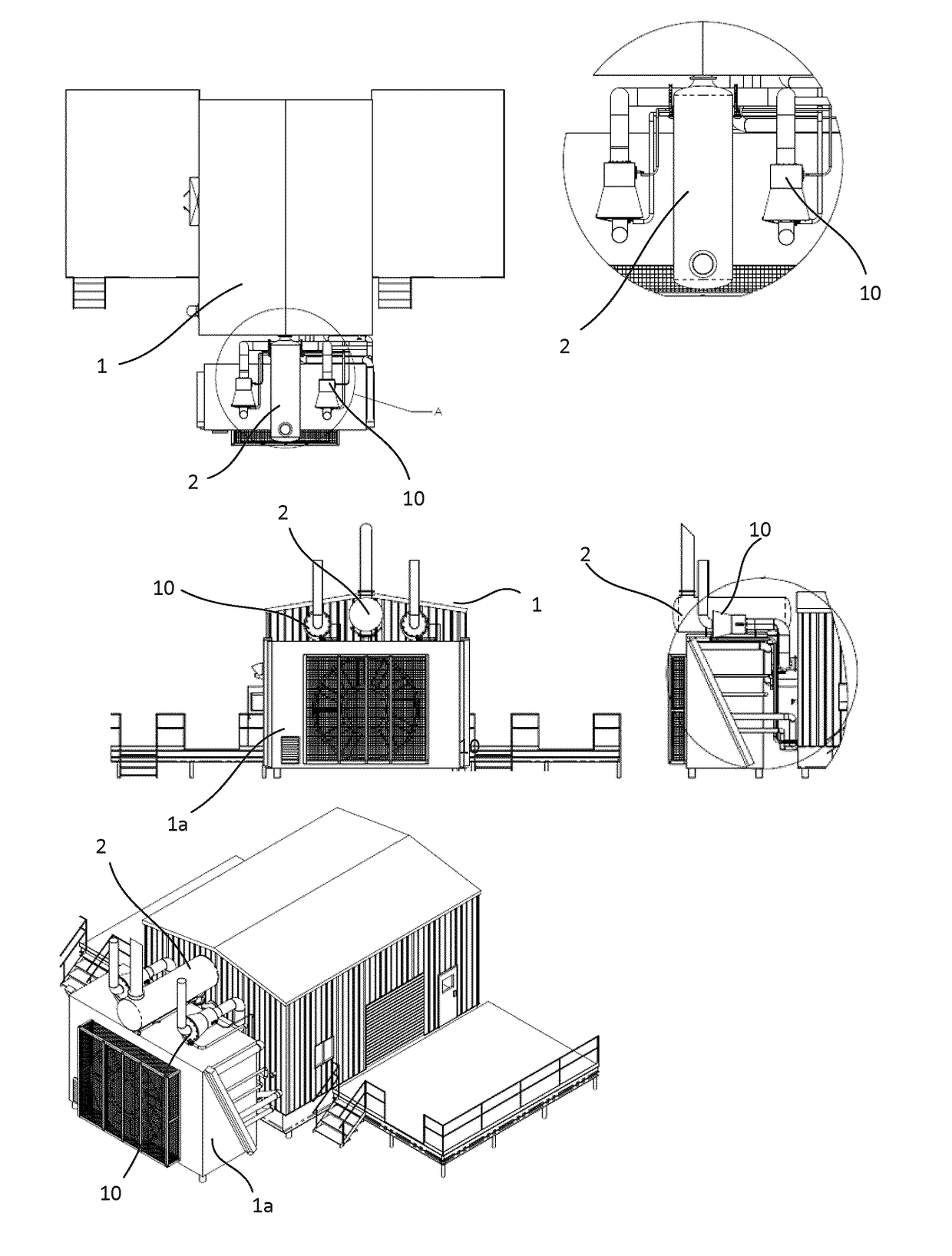
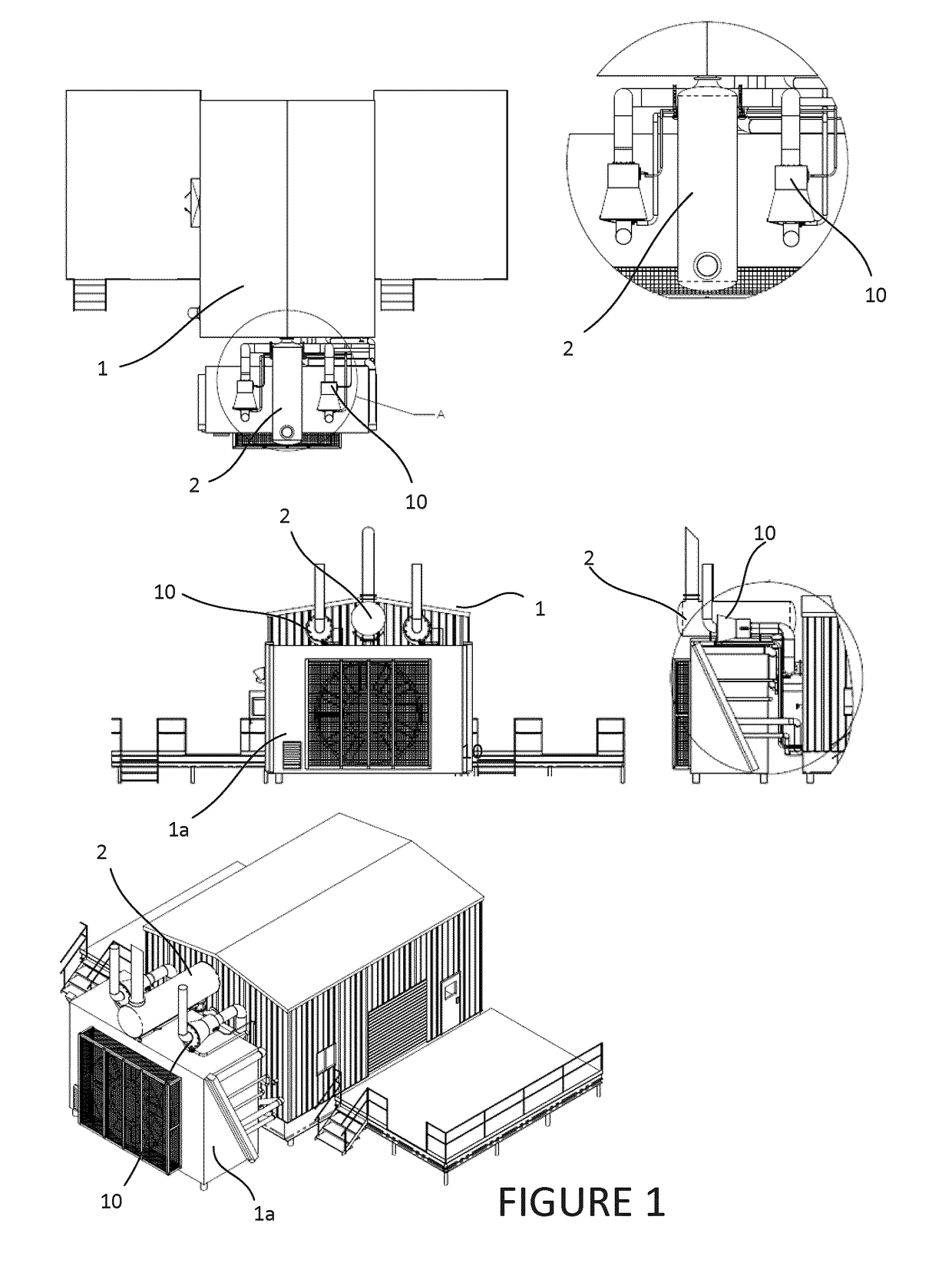
[0185]The subject invention seeks to improve the efficiency of the vaporization of waste water utilizing “waste” heat and pressure from a heat source such as an engine (e.g. an engine / generator combo unit or exhaust from steam generators, turbines, boilers, flares, flame exhaust and the like) so as to effect a reduction of the volume of raw water and the concentration of contaminants within the raw water and / or the exhaust gasses. The invention also provides a low-maintenance solution for water vaporization by reducing the effects of scaling. In addition, the invention provides effective systems and methods to muffle ICE engine noise during water vaporization processes.

[0186]In various embodiments, the invention also seeks to perform one or more of the following:[0187]a. reduce or minimize new energy input over and above the primary heat source from an ICE, combustion gas, flare gas or other similar source;[0188]b. minimize pressure drop related to water va...


PUM

PropertyMeasurementUnit
Fractionaaaaaaaaaa
Temperatureaaaaaaaaaa

Abstract

The invention relates to methods, systems and apparatus for distributed management of raw water and internal combustion engine (ICE) gas emissions generated during industrial operations. One aspect of the invention at least partially utilizes a hot gas air knife to increase or partially increase surface area between a raw water and a hot gas in order to vaporize a proportion of the aqueous phase of the raw water and concentrate contaminants within a residual raw water concentrate. The water vapor generated by the vaporization process may be demisted, discharged directly to the atmosphere or alternatively condensed and captured for use. Another aspect relates to how the liquids and gasses interact to continuously flush the surfaces of the system which may help mitigate scaling issues. The invention may help facilitate rapid transfer of ICE combustion gas particulate and ICE combustion gas chemicals onto and into the raw water as it concentrates.

Description

CROSS REFERENCE TO RELATED APPLICATIONS[0001]This application is a continuation application under 37 CFR 1.53(b) of pending prior application Ser. No. 15 / 750,664 filed Feb. 6, 2018 and claims the benefit (35 U.S.C. § 120 and 365(c)) of International Application PCT / CA2016 / 050929 filed Aug. 8, 2016, which designated inter alia the United States and which claims the priority of U.S. provisional application 62 / 202,663 filed Aug. 7, 2015, the entire contents of each application are incorporated herein by reference.FIELD OF THE INVENTION[0002]The invention relates to methods, systems and apparatus for distributed management of raw water, heat energy within combustion gas and internal combustion engine (ICE) gas heat and pressure generated during industrial operations. Such operations include but are not limited to oilfield drilling, completions and production operations with mobile, semi-permanent and / or permanent processing units. One primary aspect of the invention provides a compact, ...

Claims


Application Information

Patent Timeline
IPC IPC(8): C02F1/12B01D1/00B01D1/14B01D1/16B01D1/30B01D45/16B01D45/08B01D5/00C02F1/04C02F1/16C02F1/00
CPCC02F1/12B01D1/0058B01D1/0082B01D1/14B01D1/16B01D1/305B01D45/16B01D45/08B01D5/0003B01D5/006C02F1/048C02F1/16C02F1/008C02F2101/10C02F2101/32C02F2101/301C02F2103/10C02F2303/22C02F2209/38B01D1/30B01D53/92F22D5/00B01D3/346C02F1/10E03B1/041B01D47/06
Inventor CURLETT, JOSHUAWANLIN, HUGUES
Owner HORIZON OILFIELD SOLUTIONS
Why Eureka
Try Eureka