Vehicle horn actuation mechanism and method

a technology of horn and actuation mechanism, which is applied in the direction of mechanical control devices, process and machine control, instruments, etc., can solve the problems of inability to operate the horn, design and safety problems, and the potential for unnecessary injury to the driver's hand or face, so as to achieve reliable operation and avoid confusion with other controls

Inactive Publication Date: 2006-05-02
WECHSLER LAWRENCE I
View PDF12 Cites 10 Cited by
  • Summary
  • Abstract
  • Description
  • Claims
  • Application Information

AI Technical Summary

Benefits of technology

[0006]It is a further object of the invention to provide a horn actuation mechanism which may be operated reliably by the same hand grasping the steering wheel and in which confusion with other controls is effectively avoided.

Problems solved by technology

Such central placement of the horn actuation mechanism, however, creates design and safety problems associated with the addition of passive restraint systems requiring placement of an airbag behind the centrally located horn actuation switch.
In addition, since the centrally located horn actuation mechanism is directly in front of the airbag, in an emergency situation in which a horn is actuated by the hand of the driver and which situation concludes in an accident in which the airbag is deployed, the driver's hand will be in the path of such deployment, resulting in the potential for unnecessary injury to the driver's hand or face.
As such, a driver using a cellular phone, holding a cup of coffee or the like, or in the extreme case, a handicapped driver deprived of the use of one of his hands or arms, will be unable to operate the horn while maintaining controlled steering of the vehicle.

Method used


Image

  • Vehicle horn actuation mechanism and method
  • Vehicle horn actuation mechanism and method
  • Vehicle horn actuation mechanism and method

Examples


Embodiment Construction

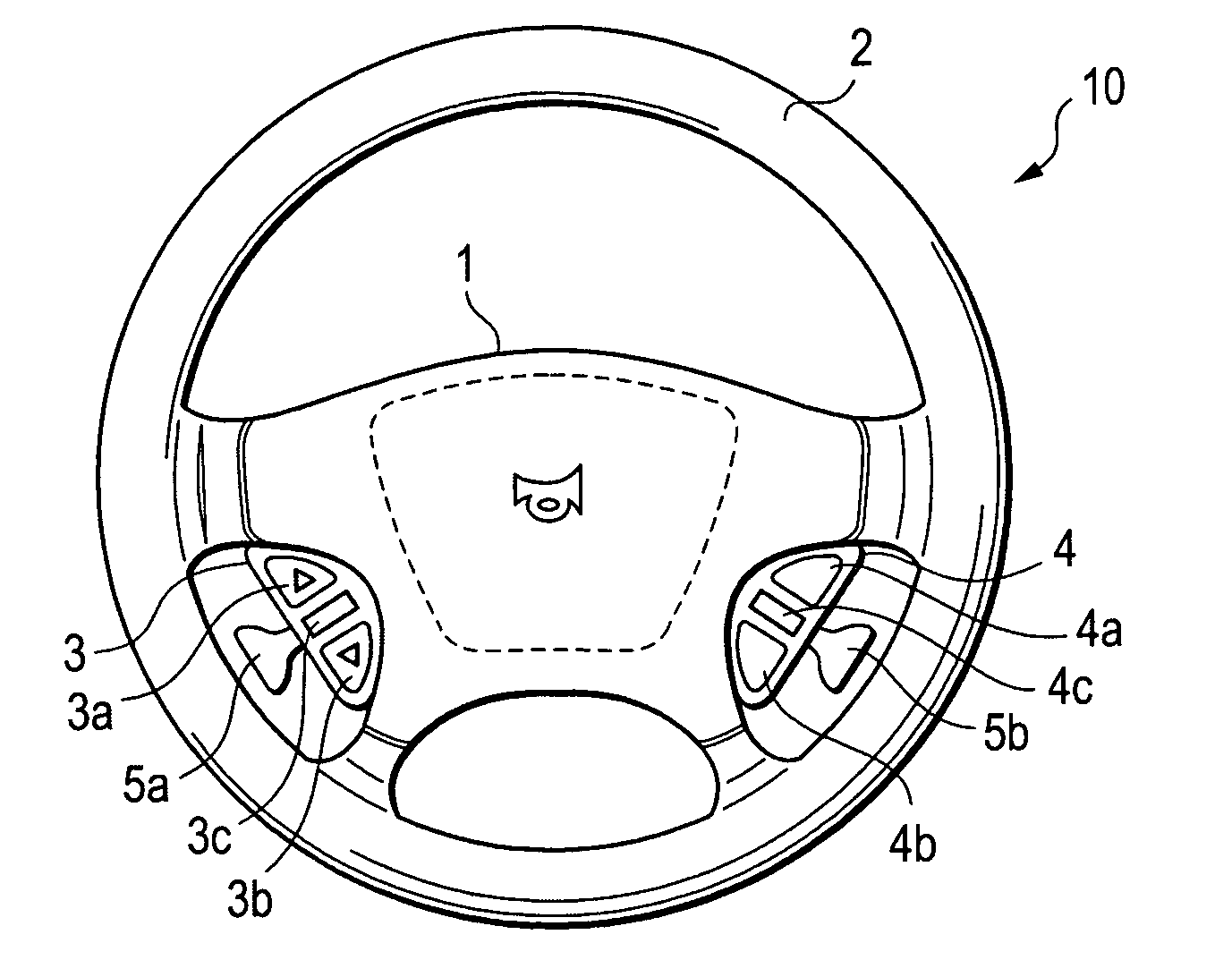
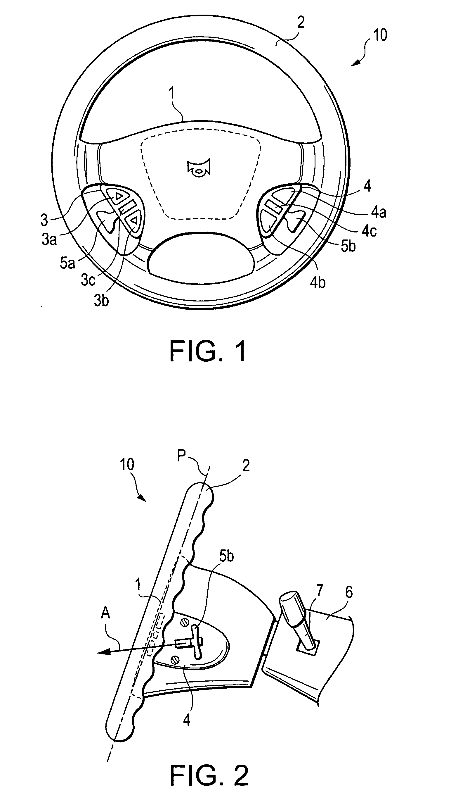
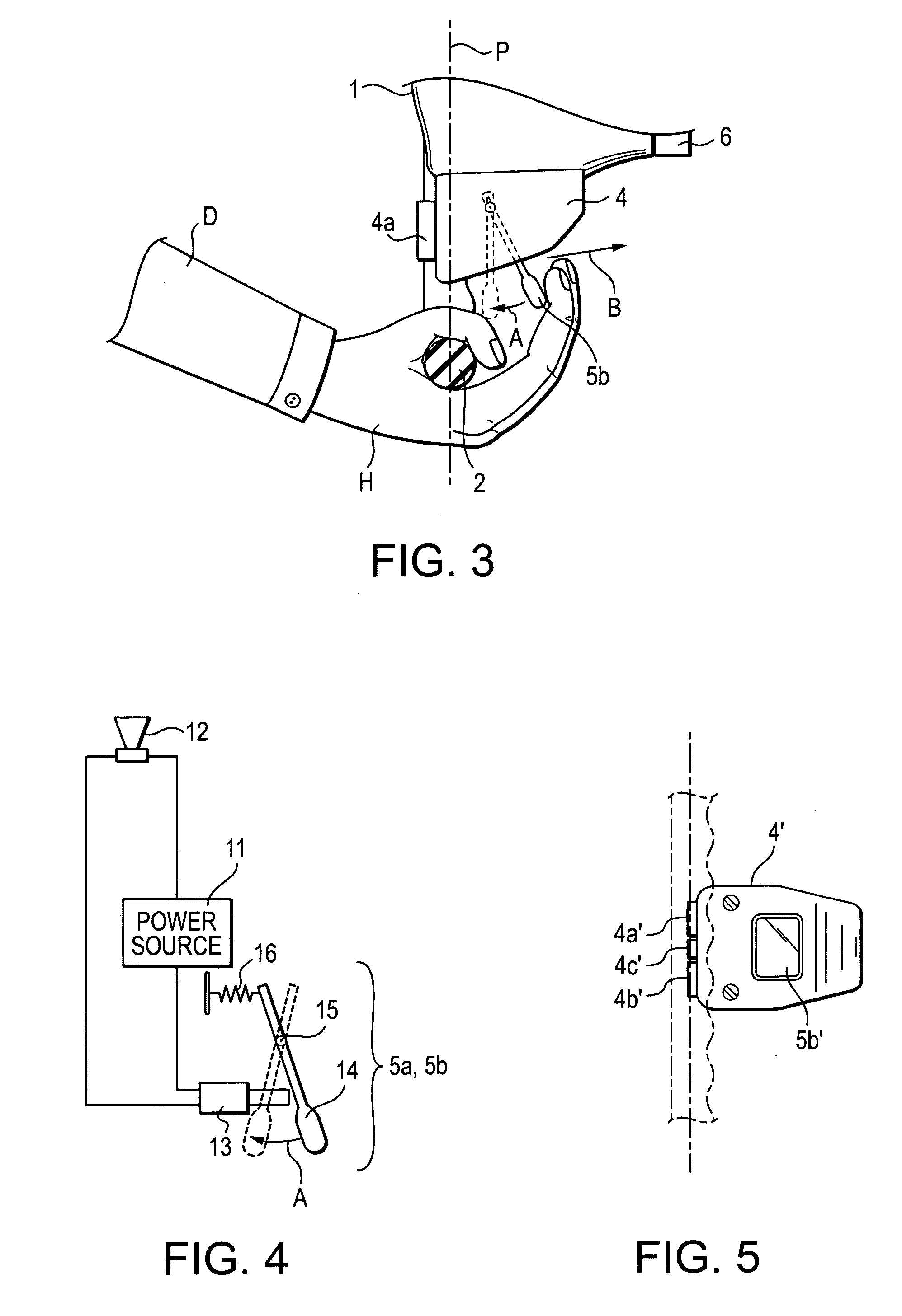
[0018]The horn actuation mechanism for use in vehicles in accordance with the invention broadly embraces a mechanism by which a deliberate movement of the hand on a side of the steering wheel plane distant from the driver can be sensed, the horn being energized in response to the sensing of such movement. For purposes herein, a “steering wheel plane” is defined as a plane arranged crosswise a rotational axis of the steering wheel and which approximates a plane bisecting a peripheral gripping region of the steering wheel. Positioning of the mechanism such that hand movement can be perceived on a side of the steering wheel plane distant from the driver, inter alia, effectively prevents confusion with other controls already conventionally located on a side of the steering wheel plane proximal to, and generally facing, the driver, such as audio controls and cruise controls of the type provided in presently available vehicles. The term “horn” herein is used broadly and generically to des...


PUM


Abstract

A horn actuation mechanism senses a deliberate movement of a driver's hand on a side of a steering plane distant from the driver, the steering wheel plane lying crossswise a rotational axis of the steering wheel and approximating a plane bisecting a peripheral gripping region of the steering wheel. The vehicle horn is energized in response to the sensing of such movement. A hand-operational portion of the horn actuation mechanism is advantageously disposed in a position in which a hand grasping a peripheral gripping portion of the wheel can simultaneously actuate the mechanism without removal of the hand from controlled contact with the wheel.

Description

CROSS REFERENCE TO RELATED APPLICATIONS[0001]This application is a continuation of application Ser. No. 09 / 560,387, filed Apr. 28, 2000 now abandoned entitled VEHICLE HORN ACTUATION MECHANISM AND METHOD, which in turn claims the benefit of U.S. Provisional Application No. 60 / 131,582 filed Apr. 29, 1999 entitled VEHICLE HORN ACTUATION MECHANISM.BACKGROUND OF THE INVENTION[0002]The present invention relates to vehicle horns, and more particularly to a method of actuating a horn, and a mechanism for implementing the method, which facilitates reliable user actuation of a horn during potentially hazardous situations.[0003]With the evolution of vehicle design, placement of the switch for actuation of a vehicle horn has been correspondingly altered to accommodate newly added or changing features. For example, many passenger vehicles are now provided with cruise controls and audio volume and channel selectors in a readily accessible position on the steering wheel to simplify selection by a ...

Claims


Application Information

Patent Timeline
Patent Type & Authority Patents(United States)
IPC IPC(8): G08B21/00B60R16/027B60Q5/00B62D1/10G05G1/04G10K15/04H01H9/06
CPCG05G1/04B60Q5/001
Inventor WECHSLER, LAWRENCE I.
Owner WECHSLER LAWRENCE I
Why Eureka
Try Eureka