Led driver current amplifier

a current amplifier and led driver technology, applied in the direction of process and machine control, identification means, instruments, etc., can solve the problems of unpredictable illumination level, ripple current is unacceptable, current amplifiers used for driving electric devices such as leds suffer from excess power dissipation, etc., to avoid image distortion, and minimize excess power dissipation

Inactive Publication Date: 2006-05-02
DELPHI TECH INC
View PDF8 Cites 26 Cited by
  • Summary
  • Abstract
  • Description
  • Claims
  • Application Information

AI Technical Summary

Benefits of technology

[0008]Illumination by LEDs is approximately proportional to the current. Linear adjustment of the current avoids image distortion caused by banding or rippling from pulse Width modulation (PWM) or other illumination source control. Typical current amplifiers suffer from power dissipation as a result of the voltage drop across the current regulating transistor; however, dynamic control of the supply voltage based on the forward voltage drop across the LEDs minimizes power dissipation.
[0009]In the exemplary embodiment, the current amplifier includes a voltage follower having a sense resistor in series with the LEDs. The sense resistor is used in order to precisely measure and regulate the current flow to the commanded current. A voltage drop measurement amplifier, for example, a differential amplifier, provides measurement of the voltage required at the delivered commanded current. A voltage-shaping amplifier biases the measured voltage drop in order to provide a biased voltage signal for controlling the switching power supply output. The bias provides voltage shaping so that the power supply voltage is regulated to not only power the LEDs, but to also avoid saturation of the linear amplifier at the commanded current and minimize excess power dissipation because of an unnecessarily high power supply voltage.
[0010]The inventive circuit may also be used to regulate current and minimize power dissipation for other electrical devices, for example, fuel injectors for a vehicle engine and deployment squibs for controlling vehicle airbag actuation.
[0011]In one form thereof, the present invention provides a circuit for powering an electrical device based on a command signal, including a power supply having a supply voltage signal connected to the device, and a current amplifier connected to the device and capable of linearly regulating current flow through the device, the supply voltage signal being regulated by the power supply based on a device voltage measured across the device, thereby minimizing power dissipation in the current amplifier.

Problems solved by technology

Typical current amplifiers used for driving electric devices such as LEDs suffer from excess power dissipation as a result of the voltage drop across the controlling device, for example a transistor.
If an inductor were added in series with an LED, the resulting ripple current would be unacceptable as the light illumination would reflect the ripple current and be captured by the imaging camera.
While it is possible to switch a current transistor on to full saturation and to have it on only for the period of illumination required by the imaging camera, such a control scheme results in an unpredictable illumination level because the current through LEDs is extremely temperature dependent.
Additionally, synchronization of the LED illumination and imaging camera in the correct proportions may be difficult.

Method used


Image

  • Led driver current amplifier
  • Led driver current amplifier
  • Led driver current amplifier

Examples


Embodiment Construction

[0024]The embodiments disclosed below are not intended to be exhaustive or limit the invention to the precise forms disclosed in the following detailed description. Rather, the embodiments are chosen and described so that others skilled in the art may utilize their teachings.

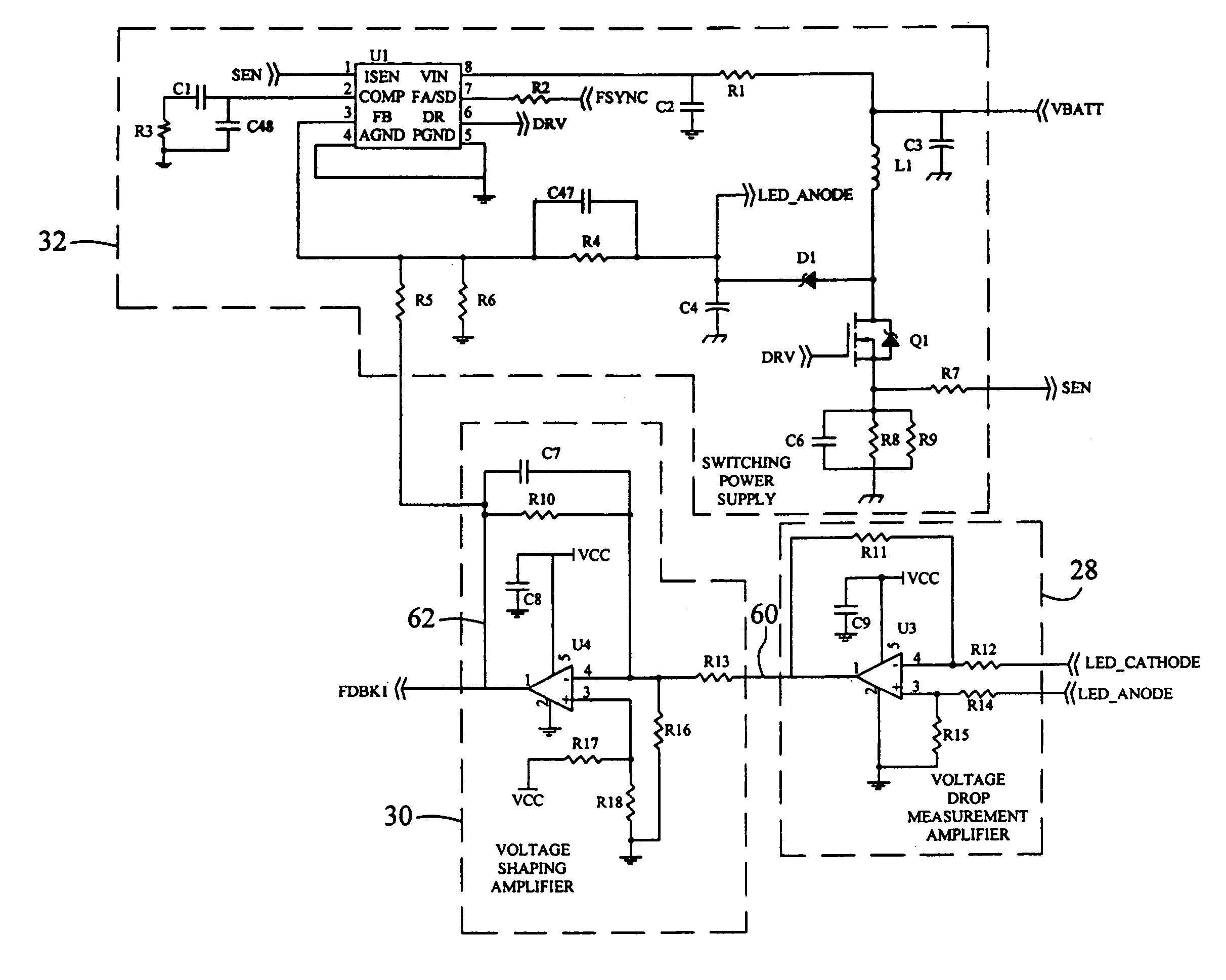
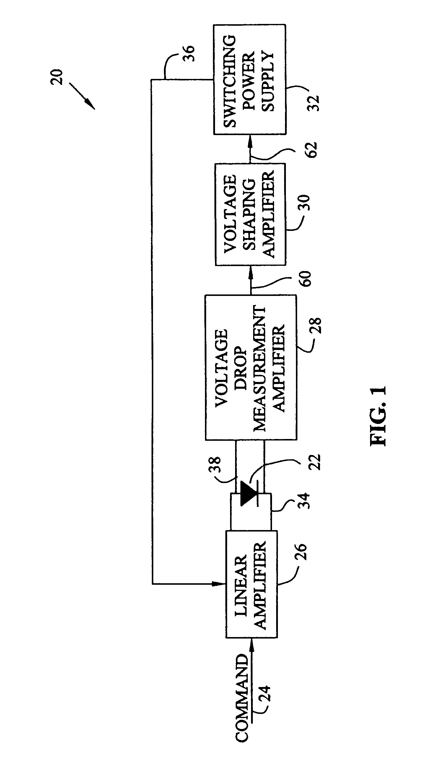
[0025]Referring to FIG. 1, exemplary circuit 20 provides control for an electrical device, for example, light-emitting diode (LED) 22, based on command signal 24. LED 22 may be a single LED or an array of LEDs, for example two series connected arrays of LEDs, or a video display screen having one or more matrices of LEDs. The term LED is defined to mean one or more LEDs.

[0026]Exemplary circuit 20 includes linear current amplifier 26, voltage drop measurement amplifier 28, voltage shaping amplifier 30, and switching power supply 32; however, the invention also contemplates a circuit with a subset of these elements. For example, command signal 24 may provide control for both current amplifier 26 and switching power...


PUM


Abstract

A circuit powering an electrical device based on a commanded current signal is provided. The circuit includes a linear current amplifier which sets a desired current flow. The circuit also dynamically controls a supply voltage in order to minimize power dissipation of the linear current amplifier. The circuit may also include a voltage drop measurement amplifier, a voltage shaping amplifier, and a switching power supply. The circuit is useful for controlling electrical devices requiring precise current control and minimal power dissipation, for example, driving light-emitting diodes (LEDs) that provide illumination inside the passenger compartment of a vehicle for an imaging occupant detection system.

Description

TECHNICAL BACKGROUND[0001]The present invention relates to a circuit for powering a device, and, more particularly, to a circuit for regulating voltage and current provided to light emitting diodes.BACKGROUND OF THE INVENTION[0002]Occupant detection systems for the passenger compartment of vehicles often include imaging systems. Some imaging systems include light-emitting diodes (LEDs) for illuminating the passenger compartment for a camera or other imaging device. Controlling the illumination provided by LEDs enables the imaging system to more accurately detect occupant presence in the passenger compartment. LED illumination is approximately proportional to the current flowing through the LED.[0003]Typical current amplifiers used for driving electric devices such as LEDs suffer from excess power dissipation as a result of the voltage drop across the controlling device, for example a transistor. Because current is regulated, the voltage drop varies from the maximum of the supply vol...

Claims


Application Information

Patent Timeline
Patent Type & Authority Patents(United States)
IPC IPC(8): G08B5/22H05B44/00
CPCH05B33/0815H05B33/0851Y02B20/347H05B45/10Y02B20/30H05B45/3725
Inventor VOREIS, THOMAS L.LI, SONGNIAN
Owner DELPHI TECH INC
Why Eureka
Try Eureka