
Image forming apparatus and droplet ejection control method

a technology of droplet ejection and forming apparatus, which is applied in the direction of printing, other printing apparatus, etc., can solve the problems of difficult to form the desired image, difficult to determine the time for avoiding image distortion in relation to various types of dot patterns, and no sufficient explanation of recording methods are given, so as to achieve the desired dot shape and print speed fast

Inactive Publication Date: 2007-05-15
FUJIFILM CORP
View PDF11 Cites 13 Cited by
  • Summary
  • Abstract
  • Description
  • Claims
  • Application Information

AI Technical Summary

Benefits of technology

[0013]The present invention is contrived in view of such circumstances, and an object thereof is to provide an image forming apparatus and a droplet ejection control method whereby image distortion caused by superimposition of dots is prevented, without increasing the recording time.

Problems solved by technology

However, if a plurality of dots are ejected so as to land in an overlapping manner on a recording medium, the ink droplets combine, the original circular shape of the dots are lost, and hence it becomes difficult to form the desired image.
In the inkjet recording apparatus disclosed in Japanese Patent Application Publication No. 3-247450, the time for avoiding image distortion is determined for each parameter, but it is extremely difficult to determine a time for avoiding image distortion in relation to various types of dot patterns.
Furthermore, no sufficient explanation of the recording method is given in cases where mixed patterns combining different dot pitches and dot sizes are formed in one image.
However, since an adjacent dot cannot be deposited onto the paper until the existing dot on the surface of the paper has dried completely, then printing takes an extremely long time.
Furthermore, since the distance between the nozzles is determined by estimating the drying time based on one set of conditions, and since this is a fixed value, it is not possible to respond to cases where different ink or paper is used.

Method used


Image

  • Image forming apparatus and droplet ejection control method
  • Image forming apparatus and droplet ejection control method
  • Image forming apparatus and droplet ejection control method

Examples


Embodiment Construction

General Configuration of an Inkjet Recording Apparatus

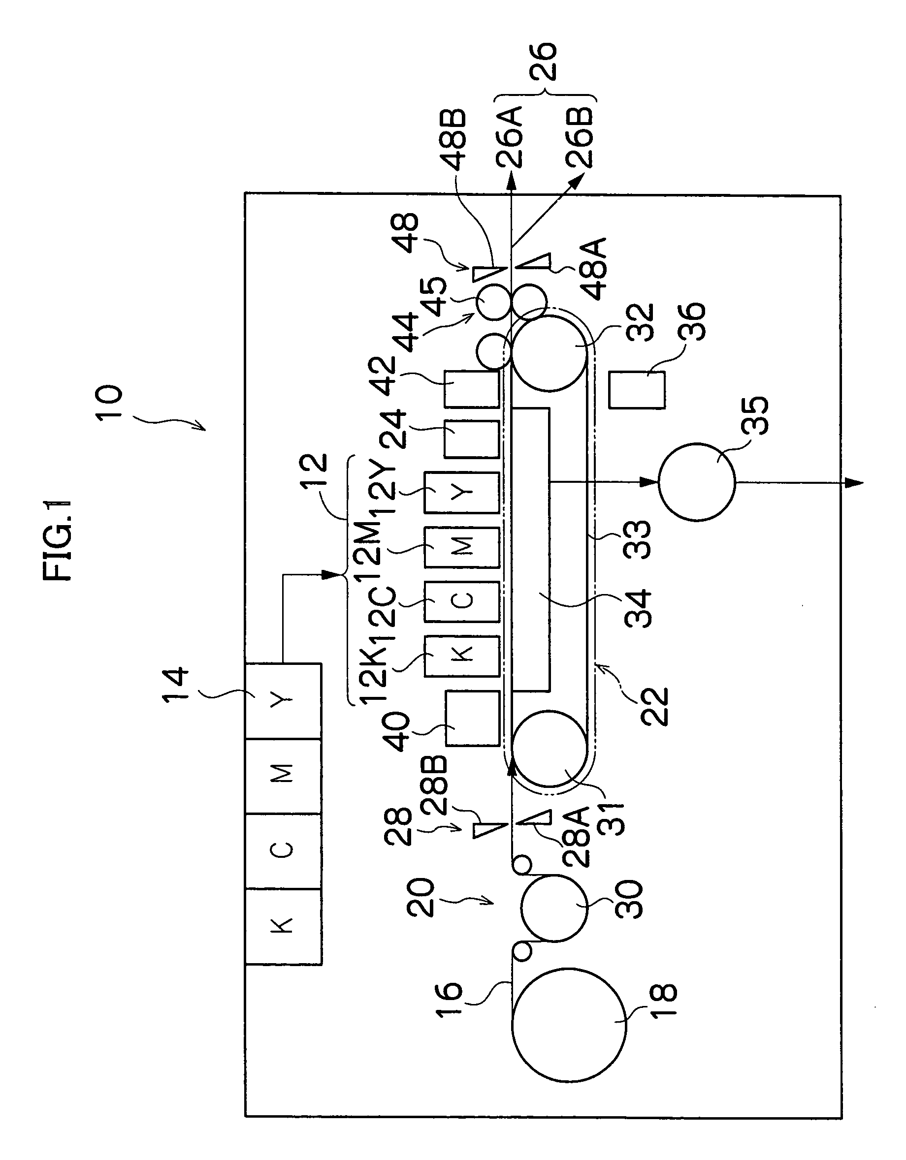
[0057]FIG. 1 is a general schematic drawing of an inkjet recording apparatus according to an embodiment of the present invention. As shown in FIG. 1, the inkjet recording apparatus 10 comprises: a printing unit 12 having a plurality of print heads 12K, 12C, 12M, and 12Y for ink colors of black (K), cyan (C), magenta (M), and yellow (Y), respectively; an ink storing / loading unit 14 for storing inks to be supplied to the print heads 12K, 12C, 12M, and 12Y; a paper supply unit 18 for supplying recording paper 16; a decurling unit 20 for removing curl in the recording paper 16; a suction belt conveyance unit 22 disposed facing the nozzle face (ink-droplet ejection face) of the print unit 12, for conveying the recording paper 16 while keeping the recording paper 16 flat; a print determination unit 24 for reading the printed result produced by the printing unit 12; and a paper output unit 26 for outputting image-printed recording paper...


PUM


Abstract

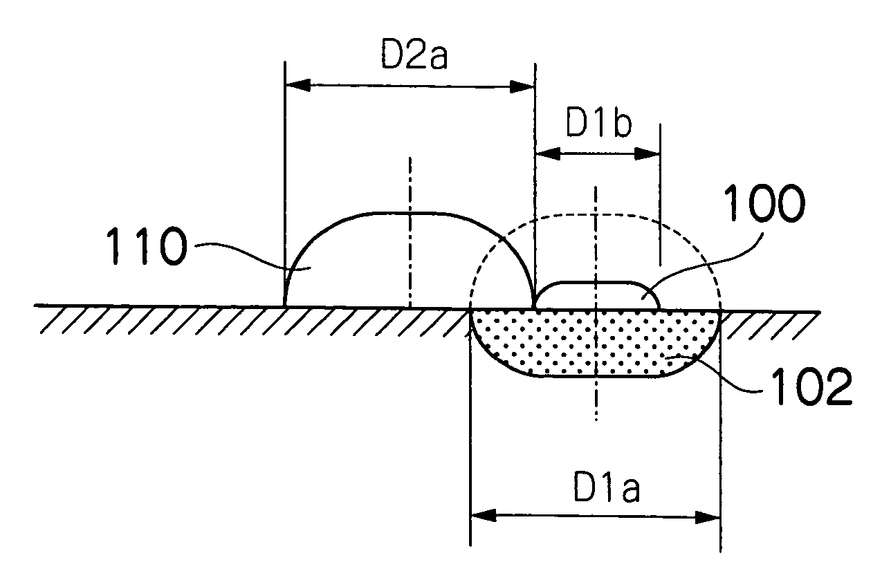
The image forming apparatus comprises: a recording head which ejects droplets of a liquid onto a recording medium; a droplet ejection control device which controls a droplet ejection timing of the recording head; and a conveyance device which relatively moves the recording medium and the recording head in a relative conveyance direction, wherein when the recording head performs ejection of a first droplet to form a first dot on the recording medium and then performs ejection of a second droplet to form a second dot overlapping with the first dot on the recording medium, the droplet ejection control device controls the droplet ejection timing of the recording head by taking a droplet diameter change time until a diameter of the first droplet deposited on a surface of the recording medium reaches D1b satisfying the following inequality as a droplet ejection time interval between the ejection of the first droplet and the ejection of the second droplet: D1b<2×Pt−D2a, where Pt is an interval between the first dot and the second dot on the surface of the recording medium, D2a is a diameter of the second droplet upon landing on the surface of the recording medium, and D1b is the diameter of the first droplet on the surface of the recording medium when the second droplet lands on the surface of the recording medium.

Description

[0001]This Non-provisional application claims priority under 35 U.S.C. § 119(a) on Patent Application No(s). 2003-332464 filed in Japan on Sep. 24, 2003, the entire contents of which are hereby incorporated by reference.BACKGROUND OF THE INVENTION[0002]1. Field of the Invention[0003]The present invention relates to an image forming apparatus and a droplet ejection control method, and more particularly to a recording control technology for an image forming apparatus for forming images by means of dots formed on a recording medium.[0004]2. Description of the Related Art[0005]Recently, inkjet recording apparatuses (inkjet printers) have become common as recording apparatuses for printing and recording images captured by digital still cameras, and the like. An inkjet recording apparatus comprises a plurality of recording elements (nozzles) in a head, the recording head being move to scan a recording medium while droplets of ink are ejected onto the recording medium from the recording el...

Claims


Application Information

Patent Timeline
Patent Type & Authority Patents(United States)
IPC IPC(8): B41J29/38B41J2/045
CPCB41J2/04503B41J2/04543B41J2/04553B41J2/0456B41J2/04573B41J2/04581B41J2002/14459
Inventor KUSUNOKI, NAOKI
Owner FUJIFILM CORP
Learn More