
Serial interface for a battery management system

a management system and serial interface technology, applied in the field of electronic devices, can solve the problems of overcharging damage to electronic devices,

Inactive Publication Date: 2006-05-02
INTERSIL INC
View PDF35 Cites 58 Cited by
  • Summary
  • Abstract
  • Description
  • Claims
  • Application Information

AI Technical Summary

Benefits of technology

[0011]In one or more of these implementations, a zero signal corresponds to a sequence of two pulses, a one signal corresponds to a sequen...

Problems solved by technology

Specifically, a battery can overheat and be damaged during the charge cycle if it is charged beyond the specified battery capacity.
Overcharging can also harm the electronic device as well as people handling the device if the battery leaks or is damaged.
In the discharge cycle, for example, an electronic device may be damaged if a short develops within the battery or the device and the sudden increase in current causes the battery or device to overheat or melt.
Unfortunately, this series resistor, though typically very small in size, consumes a significant portion of the available power delivered by the rechargeable battery over time.
Moreover, a small series resistor cannot be used to accurately detect the wide range of currents drawn by many of the electronic devices.
That is, the voltage drop produced by the very small series resistor may only be accurately detected when the current flow is high.
If the current flow is low, most conventional gas gauges may inaccurately measure the very small voltage drop across this very small resistor.
For example, the conventional gas gauge may not accurately detect the lower current used when a computer is placed in “stand-by” mode.
Although the series resistor size can be increased to increase measurement accuracy, the larger series resistor will also increase the power lost across the series resistor and, at high currents, further reduce the voltage available to drive the load.
Conventional gas gauges also have difficulty determining the battery charge when a battery is used over long periods of time.
Keeping an accurate time basis generally requires additional circuitry and added complexity in the design of the gas gauge.
Even if battery charge and other information related to charging a battery were available it is difficult to communicate these facts with other devices.
The battery and charger typically cannot communicate with other devices because there are no standards for such communication.
Further, even with communication standards provided, they are difficult and expensive to implement for typical applications.

Method used


Image

  • Serial interface for a battery management system
  • Serial interface for a battery management system
  • Serial interface for a battery management system

Examples


Embodiment Construction

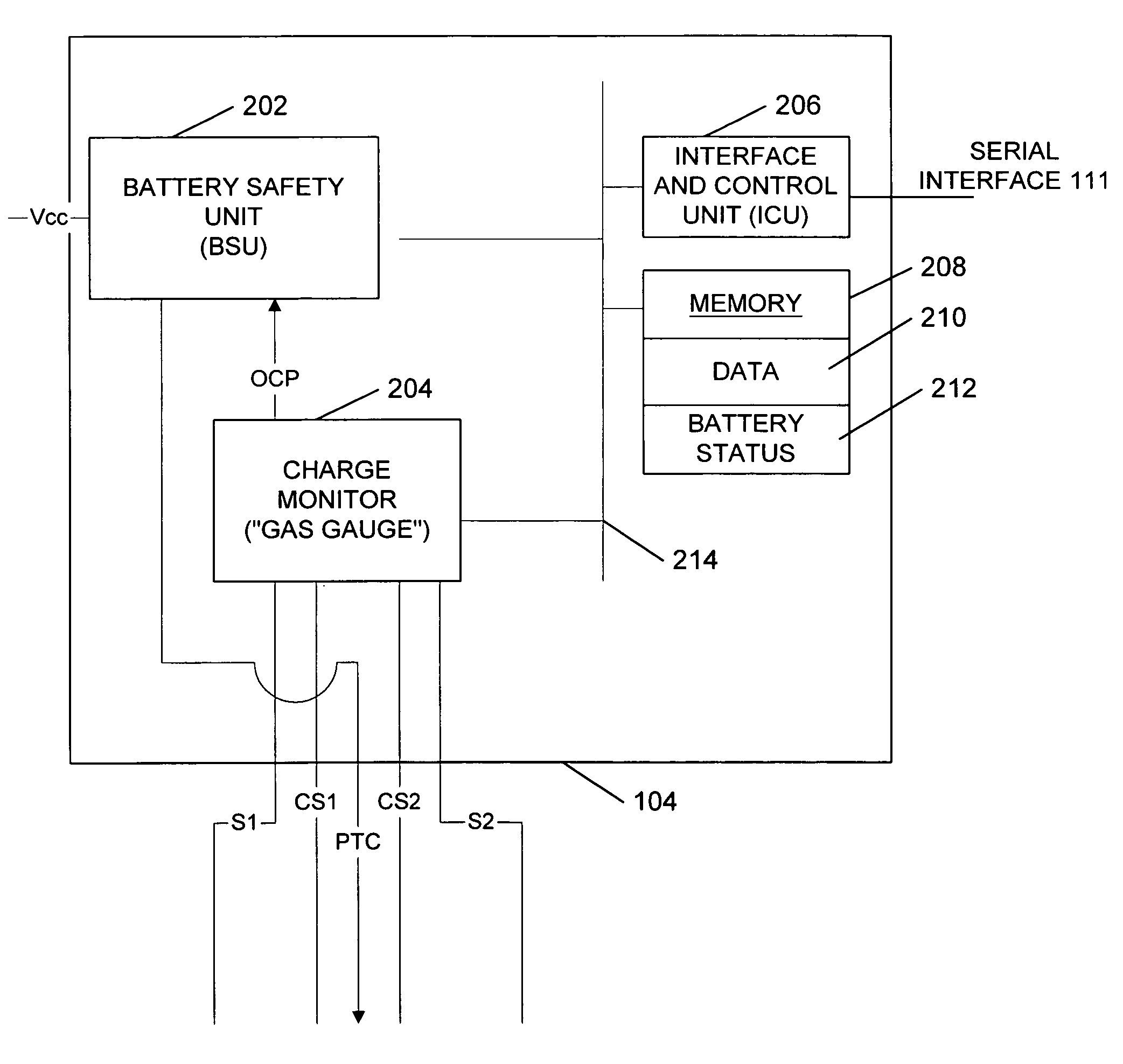
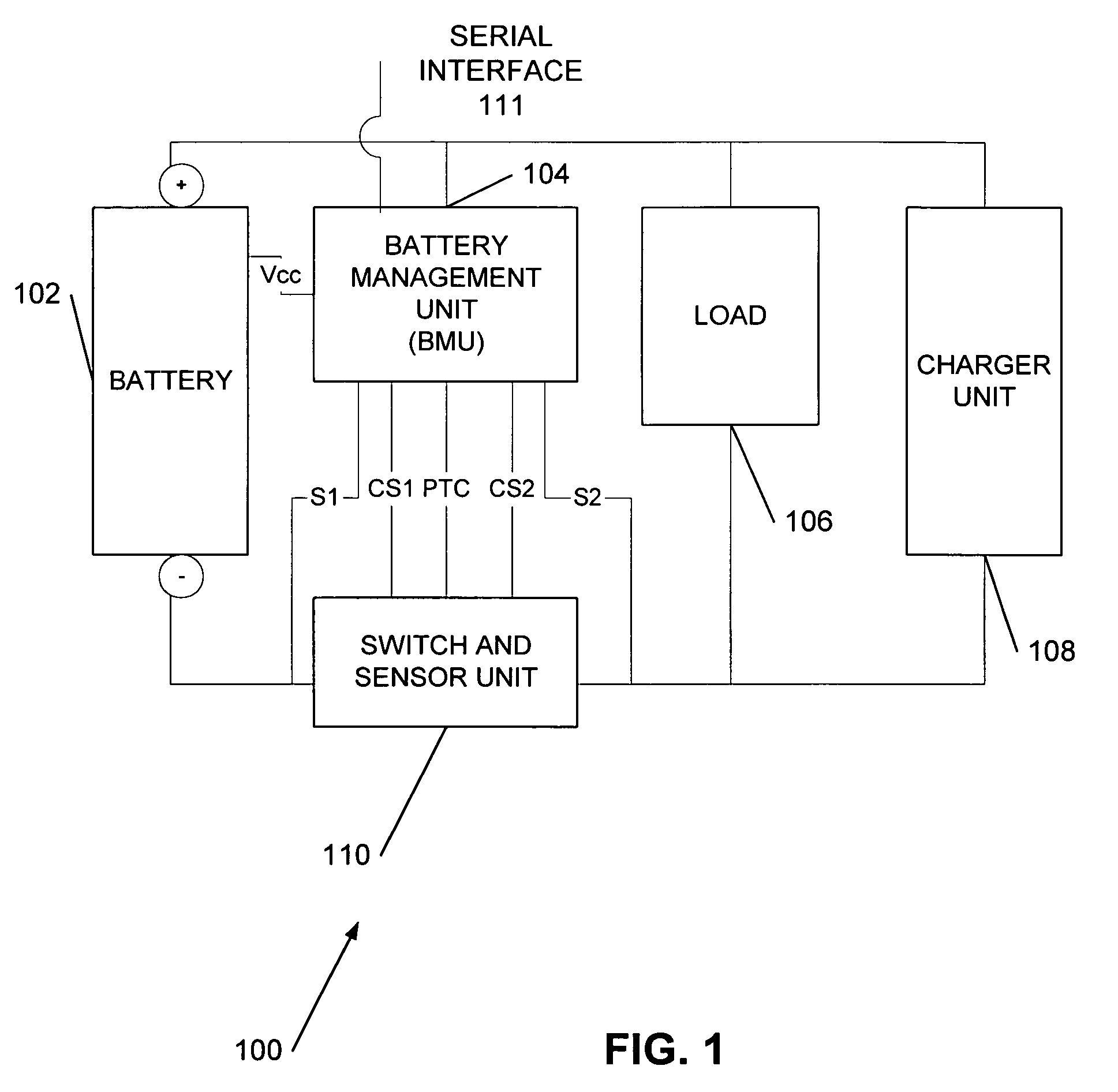
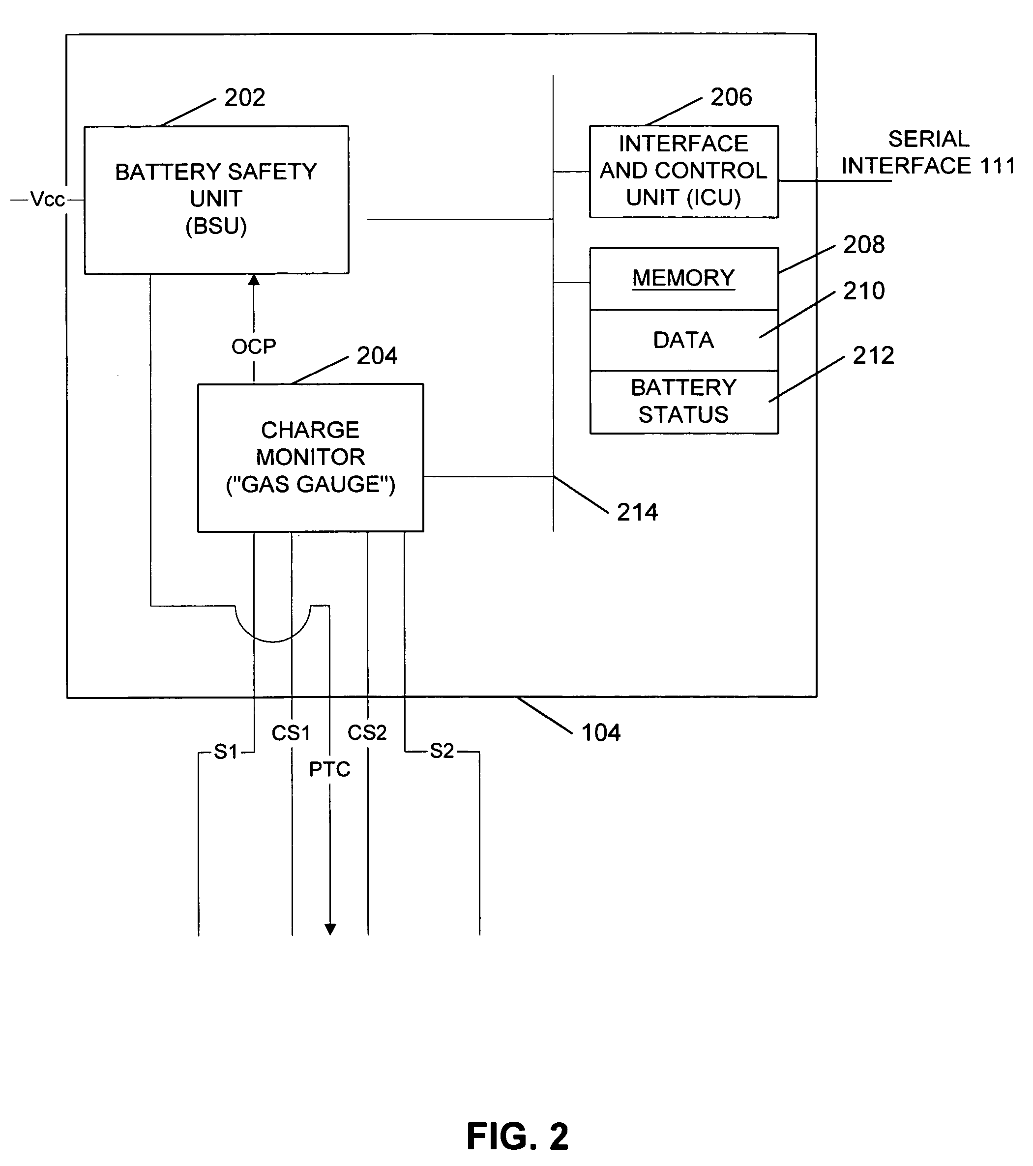
[0018]FIG. 1 provides a block diagram of a battery management system 100. Battery management system 100 includes a rechargeable battery, hereinafter battery 102, a battery management unit (BMU) 104, a load 106, a charger unit 108 for charging battery 102, and a switch and sensor unit (SSU) 110. In one implementation, BMU 104 and SSU 110 are integrated together in a single chip using customized analog, non-volatile memory, and logic circuits. Consistent with the present invention, BMU 104 and SSU 110 can be implemented by distributing logic functions to different components or using a programmable controller or central processor and bus. In general, integrating the components in battery management system 100 together makes using the system more efficient and cost-effective in a wider variety of electronic applications.

Battery

[0019]Battery 102 is a rechargeable battery typically used in electronic devices such as computers, cameras, personal digital assistants (PDA), or power tools. B...


PUM


Abstract

A serial communication method and system is provided for use with a battery management system. The system includes a port capable of sending and receiving pulses over a single conductor, serial interface logic compatible with a serial protocol and capable of generating and detecting signals on the port and communicating the signals with an internal bus in the battery management system wherein each signal in the serial protocol is defined by a specific number of pulses. In the serial protocol, a zero signal corresponds to a sequence of two pulses, a one signal corresponds to a sequence of three pulses, an acknowledge signal corresponds to a sequence of four pulses, and a start signal corresponds to a sequence of five pulses.

Description

CROSS-REFERENCE TO RELATED APPLICATIONS[0001]This application is a continuation-in-part application of, and claims priority to, U.S. Provisional Application Ser. No. 60 / 159,227, filed on Oct. 13, 1999.ADDITIONAL REFERENCES[0002]Incorporated by reference herein is the Xicor “Smart Battery Fuel Gauge / Safety Device For Cellular Phone Packs” technical reference, U.S. Pat. No. 6,522,104, entitled “Method and Apparatus for Measurement of Charge in a Battery,” assigned to the assignee of the present invention, and U.S. Pat. No. 6,501,249 B1, entitled “Battery Management System,” assigned to the assignee of the present invention. Xicor, Inc. is located at 1511 Buckeye Drive, Milpitas, Calif. 95035.TECHNICAL FIELD[0003]The present invention relates generally to electronic devices and more particularly to a method and apparatus for monitoring the charging and discharging of a battery.BACKGROUND OF THE INVENTION[0004]Rechargeable batteries are used in many applications to power a variety of de...

Claims


Application Information

Patent Timeline
IPC IPC(8): H04L23/00
CPCH02J7/0022H02J7/0004H02J7/00036H02J7/00047
Inventor DRORI, JOSEPH
Owner INTERSIL INC
Learn More