Vibrating mass gyro

a technology of vibration and mass, applied in the direction of acceleration measurement using interia force, turn-sensitive devices, instruments, etc., can solve the problems of lack of medium- and long-term stability and their use, and achieve the effect of improving stability

Active Publication Date: 2006-05-09
THALES SA
View PDF10 Cites 18 Cited by
  • Summary
  • Abstract
  • Description
  • Claims
  • Application Information

AI Technical Summary

Benefits of technology

[0004]An aim of the present invention is vibrating mass gyros with improved stability lending themselves to micro-electro-mechanical production.

Problems solved by technology

These are the least expensive rate of rotation sensors but they suffer from a lack of medium- and long-term stability inherent in their principle of operation, preventing their use, without frequent readjustments, in medium- and long-term navigation applications.

Method used


Image

  • Vibrating mass gyro
  • Vibrating mass gyro
  • Vibrating mass gyro

Examples


Embodiment Construction

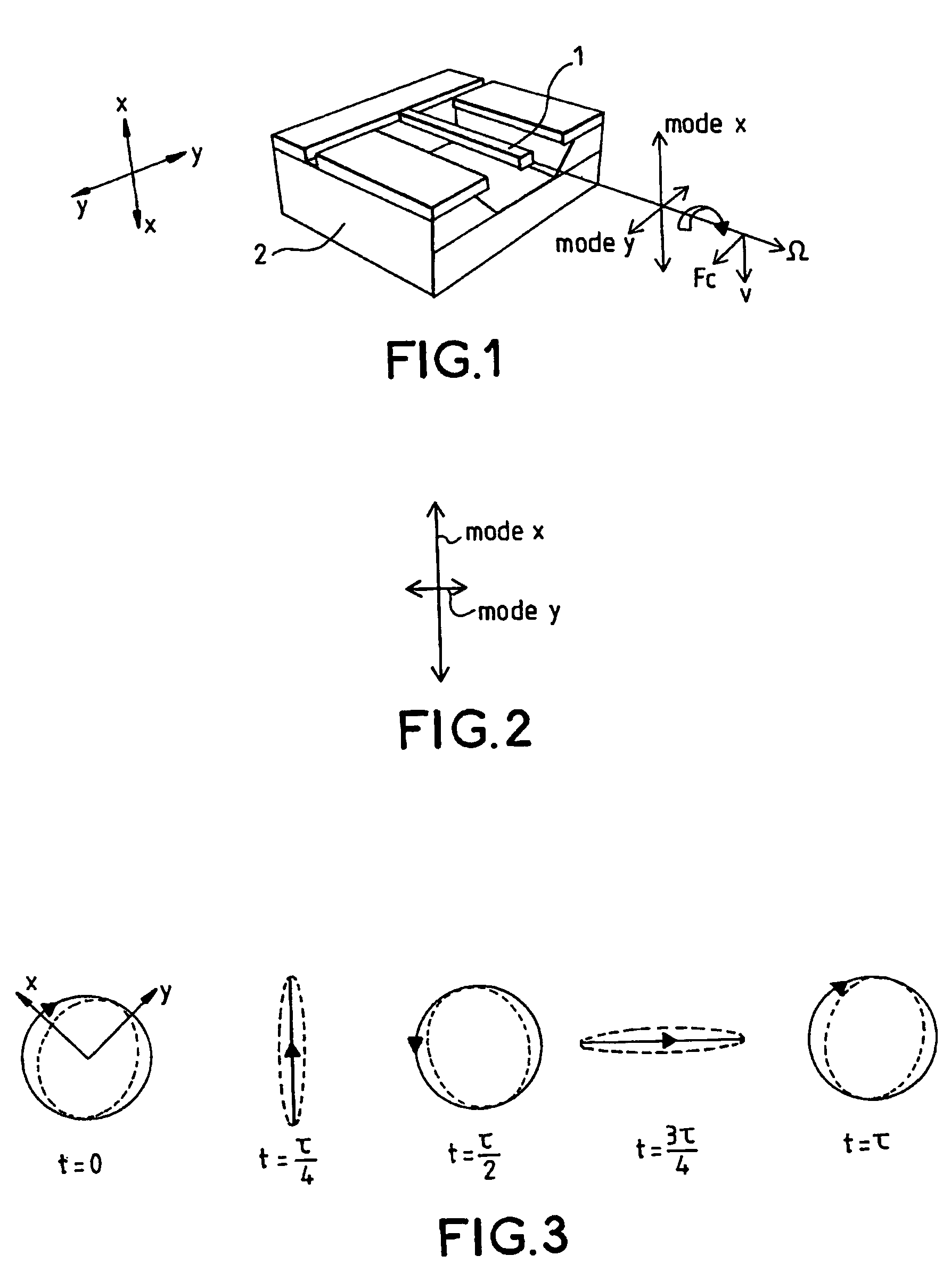
[0035]Most of the currently known vibrating mass gyros may be likened to that shown in FIG. 1 operating in the manner represented in FIG. 2.

[0036]A suspended mass represented in the form of a flexible bar 1 fixed by one end to a support 2 can oscillate according to two orthogonal modes of vibration with linear trajectories, one the x mode having a linear trajectory along an axis xx, the other the y mode having a linear trajectory along an axis yy orthogonal to the axis xx, these two modes not necessarily having identical frequencies.

[0037]The measurement technique used hitherto consists in making the suspended mass 1 vibrate according to one of the modes called the excitation mode, here the x mode, and in deducing the rate of rotation Ω of the casing of the gyro along the director axis of the xy plane, from the amplitude of the vibration of the mass in the y mode caused by the Coriolis force Fc, the y mode being called the detection mode. This measurement technique imposes limits on...


PUM


Abstract

Unlike customary vibrating mass gyros which operate by exciting a first fundamental mode of vibration of the vibrating mass and by detecting the effect of the Coriolis force on a second fundamental mode of vibration of the vibrating mass orthogonal to the first mode, this gyro operates by giving its suspended mass a circular motion alternately in the forward and reverse directions and by deducing the gyrometric effect from the difference between the apparent frequencies of the circular motion of the suspended mass in one direction and in the other. This allows a considerable reduction in the drafting of the heading measurement obtained with this type of gyro.

Description

RELATED APPLICATIONS[0001]The present application claims priority to French Application No. 03 07827 filed on Jun. 27, 2003 and is hereby incorporated by reference in its entirety into this application.FIELD OF THE INVENTION[0002]The present invention relates to the measurement of the rate of rotation of a craft by means of sensors placed on board the craft. The sensors allowing such a measurement to be made, so-called gyrometric sensors, can implement various physical principles. Three major classes of them are chiefly distinguished: that of gyro lasers, that of fiber optic gyros and that of vibrating mass gyros.BACKGROUND OF THE INVENTION[0003]The great majority of currently known vibrating mass gyros work by exciting a mode of vibration of the vibrating mass in one direction and detecting the vibrations induced in an orthogonal direction by the Coriolis force. They take multiple forms that are designed more and more often with a view to production of so-called MEMs (MicroElectroM...

Claims


Application Information

Patent Timeline
Patent Type & Authority Patents(United States)
IPC IPC(8): G01P9/04G01C9/04G01C19/56
CPCG01C19/56G01C19/5642
Inventor LEHUREAU, JEAN-CLAUDECHAUMET, BERNARDLEFORT, PIERRE-OLIVIER
Owner THALES SA
Why Eureka
Try Eureka