Wheel chock

a technology of wheel chocks and cylinders, which is applied in the field of wheel chocks, can solve the problems of inconvenient storage, inconvenient storage, and inability to meet the needs of users, and achieve the effects of convenient storage and transportation, convenient and effective use, and convenient storage and transportation

Inactive Publication Date: 2006-05-09
HOPKINS MFG
View PDF53 Cites 34 Cited by
  • Summary
  • Abstract
  • Description
  • Claims
  • Application Information

AI Technical Summary

Benefits of technology

[0007]The present invention provides an improved wheel chock that does not suffer from the problems and limitations of the prior art wheel chocks detailed above. The improved wheel chock enables easier and more effective use and more efficient storage while allowing the chocks to be manufactured in a more cost-efficient manner from light-weight, durable materials without compromising effective and dependable performance. In a preferred embodiment, the improved wheel chock presents an arcuate leading edge that better complements the contour of the chocked wheel to enable a secure chocking engagement to be achieved with minimal force exerted by the user. Additionally, in the preferred embodiment, each wheel chock can be substantially nested within another like wheel chock for easy storage and transport.
[0010]A third aspect of the present invention concerns a method of preventing rotation of wheel wherein the wheel includes a rim and a tire supported on the rim. The method broadly includes the steps of forming an arcuate leading edge along a first wheel chock, positioning the first wheel chock in an engagement position wherein the leading edge is generally transverse relative to the tire, and sliding the first wheel chock under the wheel while in the engagement position so that the leading edge presents the first point on the first wheel chock that engages the tire.

Problems solved by technology

Prior art wheel chocks are problematic and subject to several undesirable limitations.
Such physical force is undesirably time consuming, tiresome, and in some cases dangerous.
Alternatively, the prior art chocks can simply be placed under the wheel, without forcing them into a secure engagement with the majority of the tire treads, however, this is highly undesirable in most applications as the heavy vehicle is then subject to movement before the majority of treads engage the chock to thereby prevent such movement.
Such settling movement can is some cases cooperate with the weight of the vehicle to cause the chock to catastrophically fail or become dislodged, potentially enabling the vehicle to roll uncontrollably.
This is particularly problematic on inclined surface applications.
Although larger wheel chocks constructed of heavier, stronger materials can reduce the risks of chock failure, such configurations compound the problems associated with forcing the chock under the tire detailed above.
All prior art wheel chocks, including relatively smaller, compact chocks, are undesirably difficult to transport and / or store particularly when used in a pair, or plurality of chocks, as is typically desired.
For example, the solid surfaced, closed body configurations are space consuming and the generally triangular shape, as is preferred, is not conducive to interengaging a pair of chocks for transport and / or storage.
However, such interconnection does not enable the chocks to be used independently from one another, for example, on separate wheels.

Method used


Image

  • Wheel chock
  • Wheel chock
  • Wheel chock

Examples


Embodiment Construction

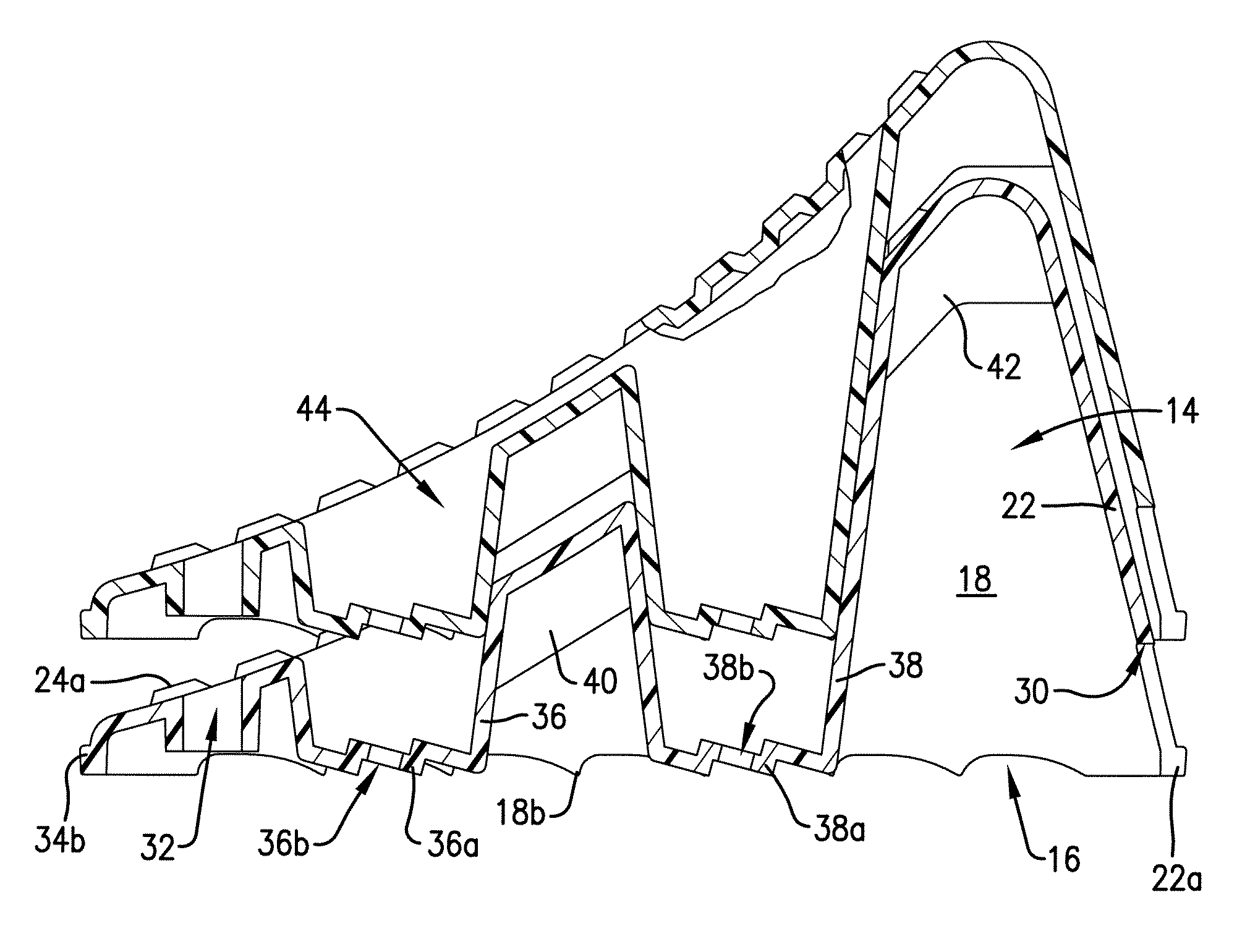
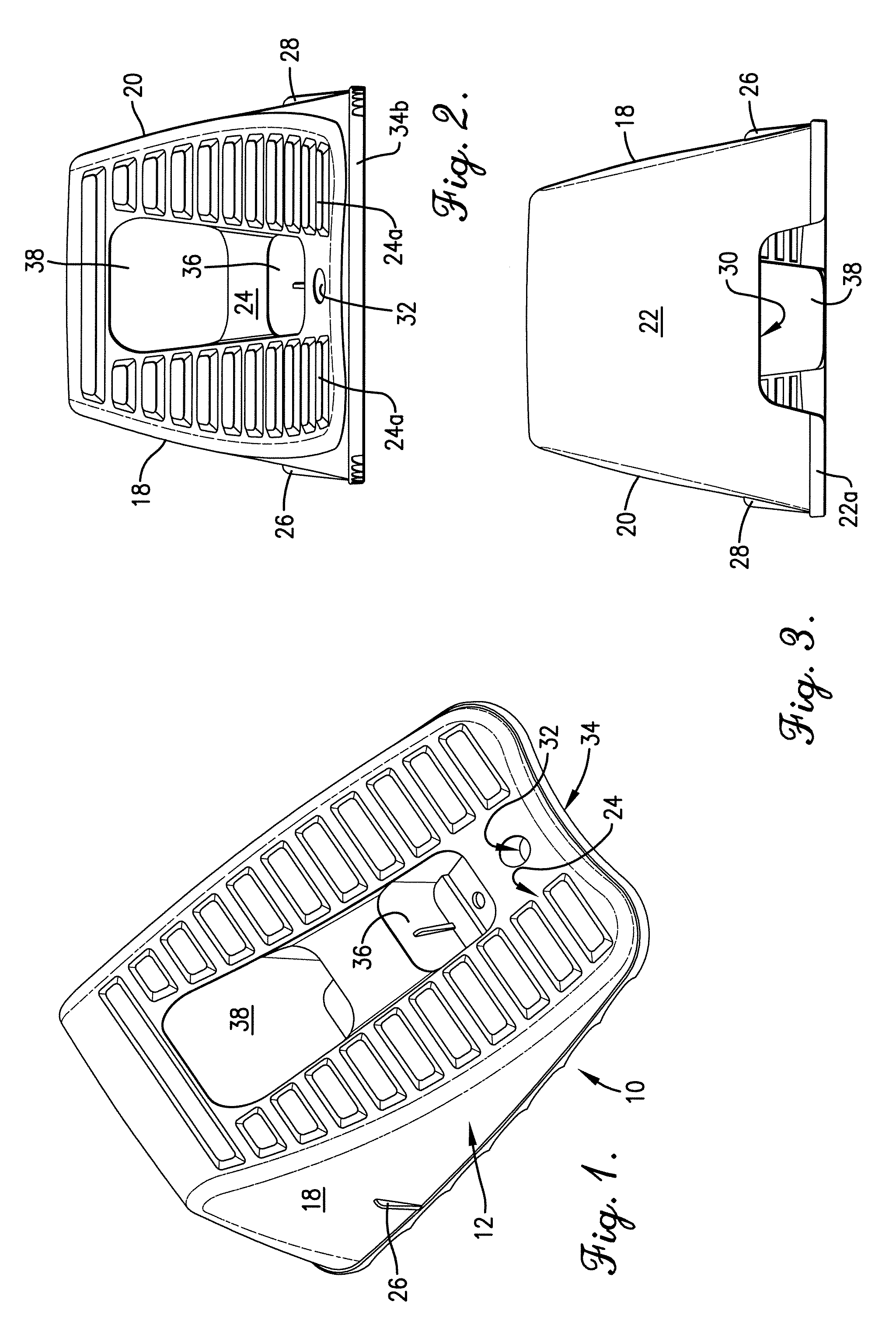
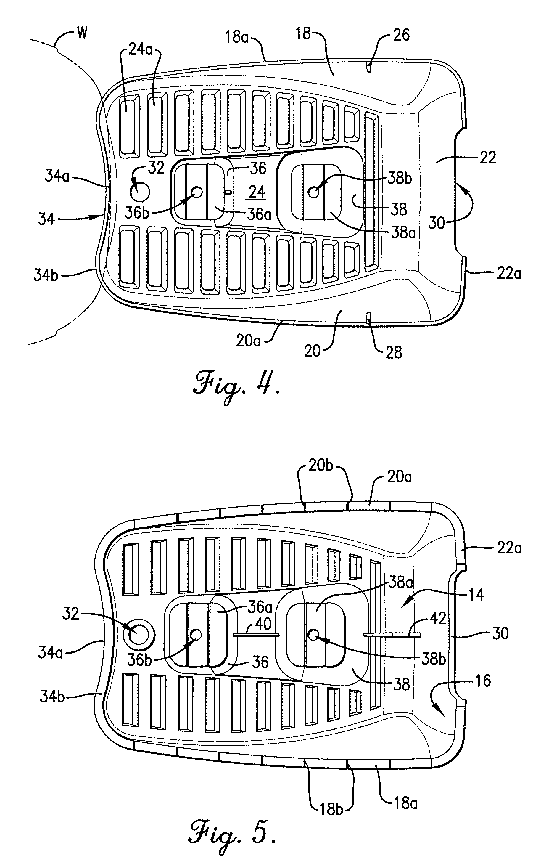
[0020]FIG. 1 illustrates a wheel chock 10 constructed in accordance with the principles of a preferred embodiment of the present invention and configured for placement under a resting wheel W (see FIGS. 4 and 6) to maintain the wheel W at rest. While the wheel chock 10 is illustrated in use with a rubber tired wheel W, such as a wheel found on a powered vehicle, the principles of the present invention are not limited to use with any particular type of wheel and are equally applicable to prevent undesired movement of virtually any wheel rimmed, tired, or otherwise as well as any wheel-like structure. Additionally, while the improved wheel chock of the present invention is particularly well suited for transporting in a utility vehicle, such as a fire fighting vehicle, dump truck, wrecker, or recreational vehicle, for onsite use to prevent undesired movement of the resting vehicle during operation, such as fighting a fire, loading or unloading, or camping, the principles of the present...


PUM


Abstract

A wheel chock (10) configured for placement under a resting rubber tired wheel (W), such as a wheel found on a powered vehicle, to maintain the wheel (W) at rest is disclosed. The wheel chock (10) broadly includes a body (12) that defines an internal chamber (14) in communication with an open face (16) presented by the body (12). The body (12) presents a prism-like configuration having a generally triangular shape and includes a pair of oppositely spaced sidewalls (18, 20), a rear wall (22) extending between and adjoining the sidewalls (18,20), and a wheel-supporting surface (24) extending between and thereby enclosing the walls (18,20,22). The wheel-supporting surface (24) presents a low profile, arcuate leading tire-engaging edge (34). The arcuate leading edge (34) substantially complements the contour of the tire and enables the chock (10) to be easily placed under the wheel (W) in an optimal operating position i.e., in close adjacent alignment with the wheel (W) so that at least a portion of the majority of the circumferentially extending treads of the rubber tire of the wheel (W) engage at least a portion of the chock (10) with a minimal exertion of force and effort by the user. The internal chamber (14) in communication with the open face (16) enables the body (12) of the chock (10) to be stackably nested within another similarly configured wheel chock to provide a compact, space-efficient storage of the chocks that facilitates ready portability for transportation of a pair or more of the chocks in the vehicle.

Description

BACKGROUND OF INVENTION[0001]1. Field of the Invention[0002]The present invention relates generally to wheel chocks. More specifically, the present invention concerns an improved wheel chock presenting a unique configuration that enables easier and more effective use and more efficient storage while allowing the chocks to be manufactured in a more cost-efficient manner from light-weight, durable materials.[0003]2. Discussion of Prior Art[0004]Conventional wheel chocks are known in the art and generally include an external device, typically presenting a triangular configuration, that is positioned in contact with a rubber tired wheel at rest, to maintain the wheel at rest within the design limitations of the chock. It is known in the art to utilize one or more wheel chocks (e.g., placed under one or both sides of one or more wheels) to prevent undesired movement of a resting vehicle, such as a fire fighting vehicle, dump truck, wrecker, recreational vehicle, etc., or other wheeled de...

Claims


Application Information

Patent Timeline
Patent Type & Authority Patents(United States)
IPC IPC(8): B60T3/00
CPCB60T3/00
Inventor CHRISCO, LARRY L.FORBIS, CHARLIE L.
Owner HOPKINS MFG
Why Eureka
Try Eureka