
Cartridge reel with internal reel assembly lock

a drive system and cassette reel technology, applied in the field of data storage tape drive system, can solve the problems of increased friction and heat stress on the brake body components, reduced service life, and increased travel required for shifting the brake body

Active Publication Date: 2006-05-09
ORACLE INT CORP
View PDF4 Cites 23 Cited by
  • Summary
  • Abstract
  • Description
  • Claims
  • Application Information

AI Technical Summary

Benefits of technology

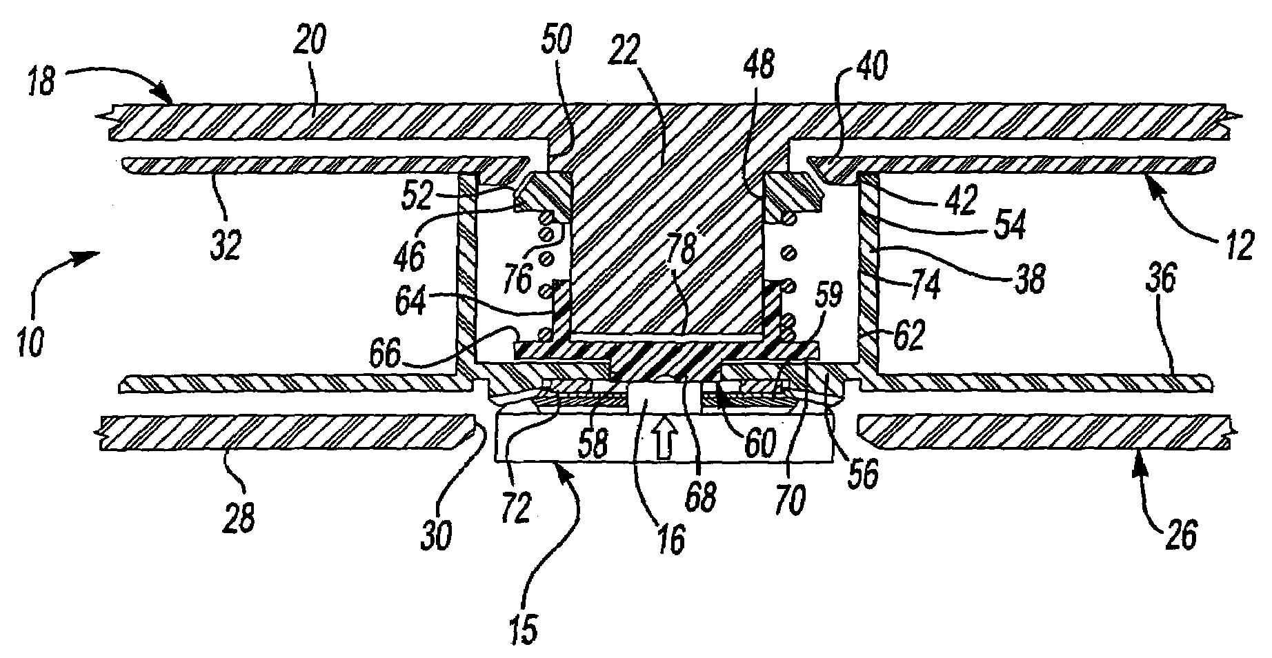
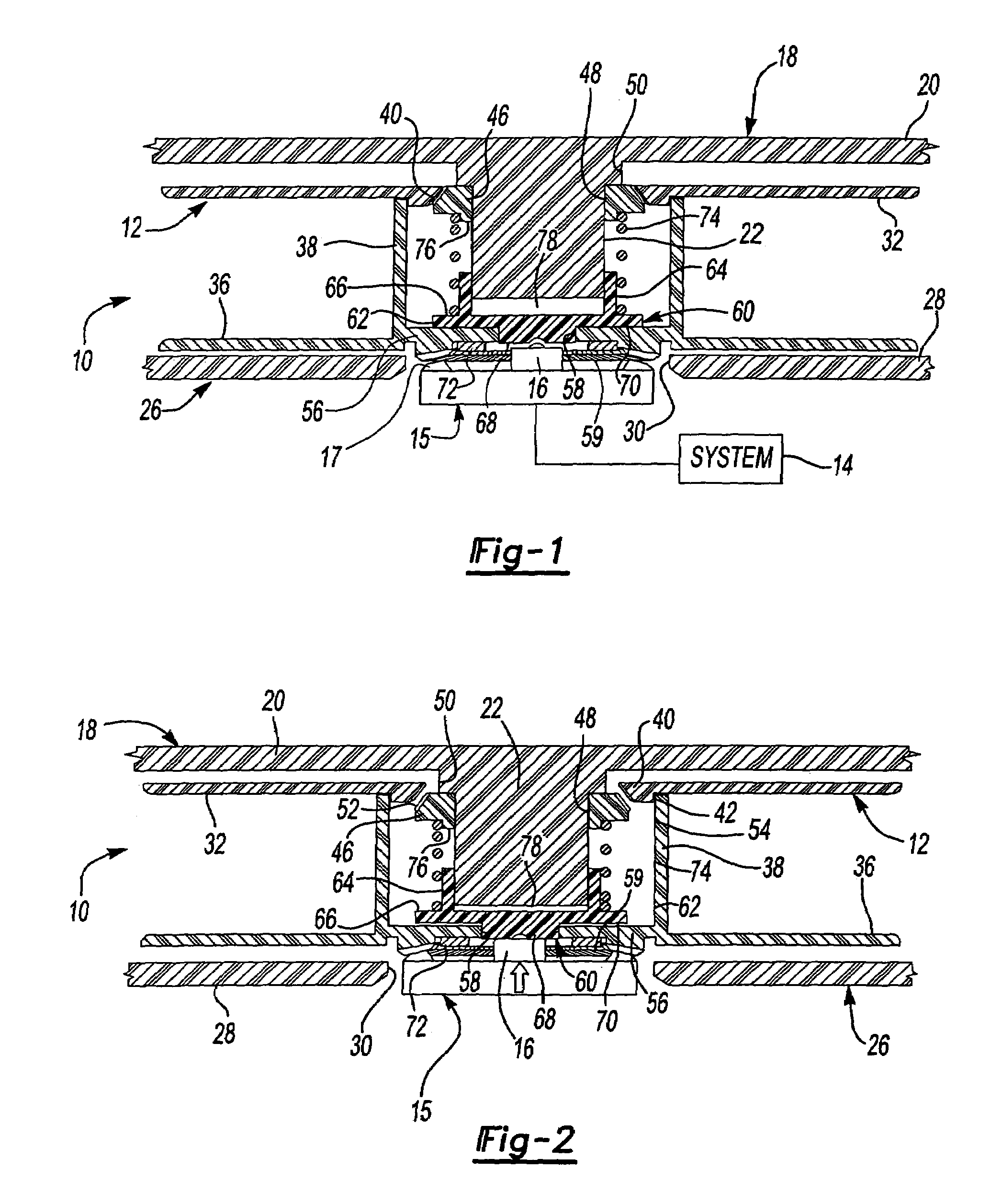
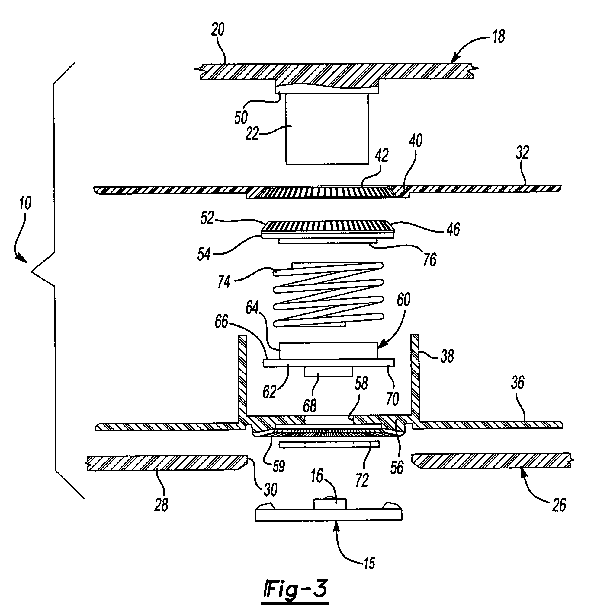
[0013]According to other aspects of the invention, the first and second rings of teeth are complementary sets of beveled gear teeth. The first ring of teeth are preferably formed on the inner diameter of the first flange of the tape reel and, in accordance with one embodiment of the invention, are inclined at approximately a 45° angle relative to the axis of rotation of the tape reel. The second ring of teeth are outwardly directed teeth formed on a circular member attached to the central boss. The second ring of teeth, in accordance with one embodiment of the invention, are also beveled gear teeth oriented at a 45° angle relative to the axis of rotation of the tape reel. The inwardly directed first ring of teeth and the outwardly directed second ring of teeth may be engaged and disengaged within a minimum range of movement. The extent of travel of the tape reel within the cartridge is limited by the spacing between the end of the central boss and the drive hub engaging member. In this way, the reel may be both unlocked and centered relative to the cartridge in the same movement.

Problems solved by technology

Potential problems arise when higher drive hub speeds are achieved.
Higher hub rotation speeds may cause increased friction and heat stress on the brake body components.
A disadvantage of this system is that substantial travel is required to shift the brake body against the spring to release the teeth on the brake body from the teeth of the tape reel.

Method used


Image

  • Cartridge reel with internal reel assembly lock
  • Cartridge reel with internal reel assembly lock
  • Cartridge reel with internal reel assembly lock

Examples


Embodiment Construction

)

[0018]Referring to FIG. 1, a data storage tape cartridge 10 is shown in a fragmentary view. The data storage tape cartridge 10 is of the single reel type and is normally provided as a flat, rectangular, box-shaped cartridge. A tape reel 12 is provided within the tape cartridge 10. The data storage tape cartridge 10 is designed to be used with a data storage system 14 that is diagrammatically represented in FIG. 1 by the box labeled “system”. The system 14 includes a drive hub 15 that is driven by a motor as is well known in the art. The drive hub 15 includes a reel contact member 16 and a plurality of gear teeth 17.

[0019]The data storage tape cartridge 10 includes a housing that is molded in two parts. A first housing part generally referred to by reference numeral 18 includes a first wall 20 and a central boss 22. The second housing part includes a second wall 28 of the tape cartridge 10 that defines a central aperture 30 that is coaxially aligned with the central boss 22.

[0020]Th...


PUM


Abstract

A data storage tape cartridge for a high speed tape drive. The tape cartridge encloses the tape reel having a drive hub that defines a reel lock. A ring of beveled gear teeth on the tape reel engage a ring of beveled gear teeth affixed to the tape cartridge for locking the reel to the cartridge. A spring biases the teeth into engagement. When the data storage tape cartridge is inserted into a data storage system, a drive hub engages the tape reel to shift the tape reel relative to the tape cartridge and disengage the rings of beveled gear teeth. In the same motion, the tape reel is centered within the data storage tape cartridge and a hub engagement member is lifted off of a flange of the tape reel.

Description

BACKGROUND OF THE INVENTION[0001]1. Field of the Invention[0002]The present invention relates to a data storage tape drive system having a locking mechanism for locking the reel within the tape cartridge when the tape cartridge is not in a tape drive system.[0003]2. Background Art[0004]Data storage tape drive systems are used to store large volumes of information for subsequent retrieval and use. Data storage tape drive systems are used to store computer data, audio files, and video files.[0005]Data storage tape drive systems generally include interchangeable data storage tape cartridges that are selectively loaded into a tape drive system to store or retrieve data. Data storage tape cartridges generally include a housing, a tape reel, and magnetic storage tape that is wound on the tape reel. Tape drive systems generally include one or more drive hubs that are configured to operatively engage the data storage tape cartridge and rotate the tape reel. The drive hub is driven by a driv...

Claims


Application Information

Patent Timeline
IPC IPC(8): G11B23/04
CPCG11B23/043
Inventor VENO, WILLIAM T.MORGAN, PHILLIP M.
Owner ORACLE INT CORP
Learn More