Negative pressure boosting device

Inactive Publication Date: 2006-05-09
BOSCH AUTOMOTIVE SYST CORP
View PDF16 Cites 0 Cited by
  • Summary
  • Abstract
  • Description
  • Claims
  • Application Information

AI Technical Summary

Benefits of technology

[0012]It is an object of the present invention to provide a negative pressure boosting device capable of performing improved boosting control, with shortening the stroke of an inpu

Problems solved by technology

Therefore, the atmosphere is introduced into the variable pressure chamber through the open atmospheric valve, resulting in a pressure difference between the variable pressure chamber and the constant pressure chamber.
This makes the output shaft and the input shaft of the negative pressure boosting device longer and, as a result, makes the pedal stroke longer.
However,

Method used


Image

  • Negative pressure boosting device
  • Negative pressure boosting device
  • Negative pressure boosting device

Examples


Embodiment Construction

[0032]Hereinafter, embodiments of the present invention will be described with reference to the attached drawings.

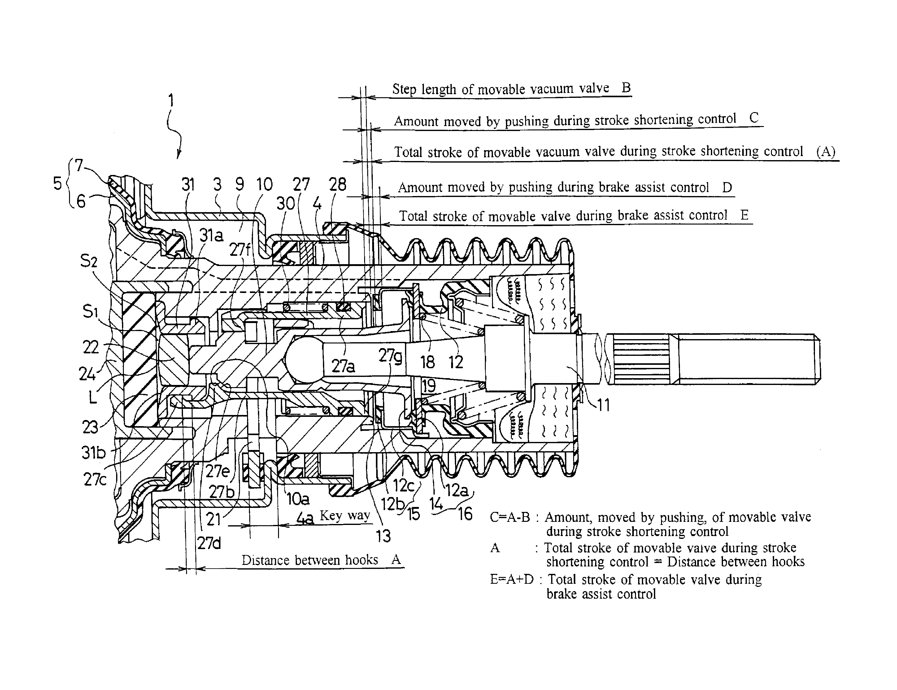
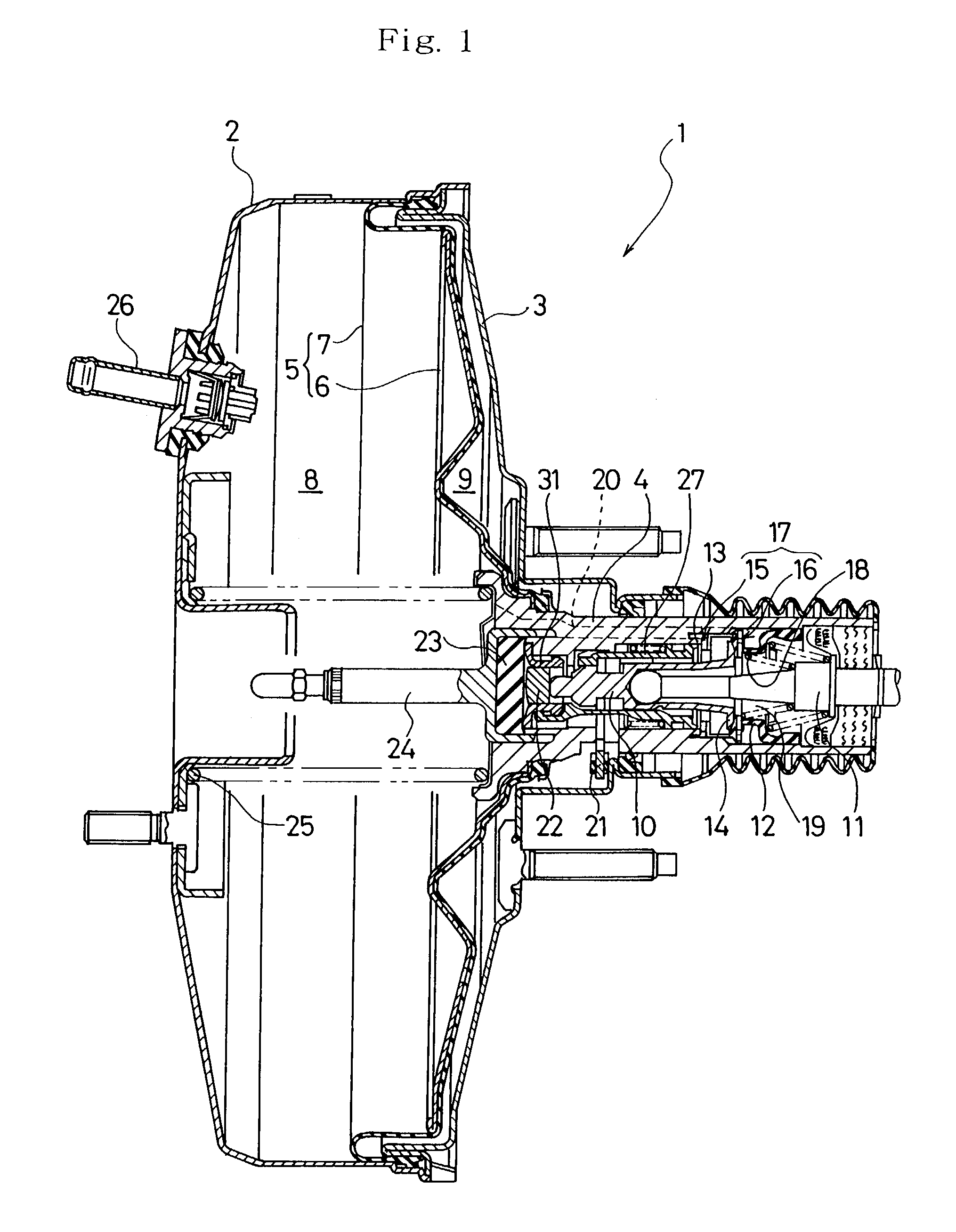
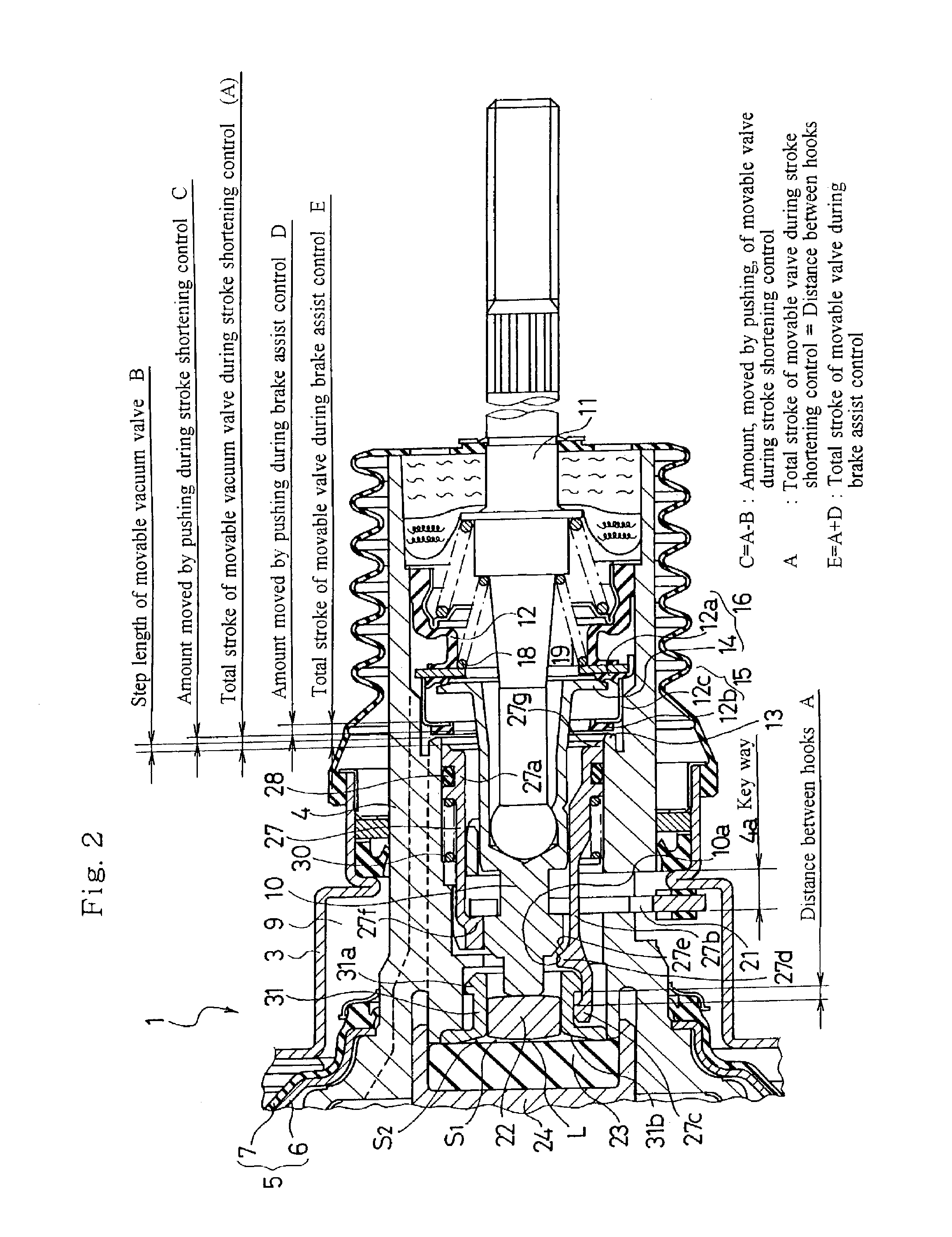
[0033]FIG. 1 is a sectional view showing an embodiment of a negative pressure boosting device according to the present invention in its inoperative state, FIG. 2 is an enlarged sectional view showing a portion including a vacuum valve and an atmospheric valve in the negative pressure boosting device shown in FIG. 1, FIG. 3 is a sectional view partially showing the operative state of a cylindrical member in the negative pressure boosting device shown in FIG. 1, and FIGS. 4(a)–4(c) are illustrations for explaining the operation of hooks in the negative pressure boosting device shown in FIG. 1, wherein FIG. 4(a) is a sectional view partially showing the inoperative state where the hooks are not engaged with each other, FIG. 4(b) is a sectional view partially showing a state on the way of operation, and FIG. 4(c) is a sectional view partially showing the state where the hook...


PUM


Abstract

In a negative pressure boosting device of the present invention, upon depression of a pedal at a normal speed, an input shaft 11 and a valve plunger 10 move forward to close a vacuum valve 15 and open an atmospheric valve 16 and a power piston 5, a valve body 4, and an output shaft 24 move forward. In the initial stage of operation, hooks 27c and 31a are not engaged with each other so that a cylindrical member 27 does not move forward, thereby shortening the stroke of the input shaft 11 as compared to a conventional one. Upon rapid depression of the pedal, a press face 10a presses a pressed face 27e so as to deform an engaging arm portion 27b, thereby disengaging the hooks 27c and 31a from each other. The cylindrical member 27 is moved backward by a spring 30 to push a vacuum valve portion 12b so that the atmospheric valve portion 12a is spaced apart from the atmospheric valve seat 14 more rapidly than that of the service braking, thereby increasing the jumping amount and thus rapidly intensifying the output.

Description

BACKGROUND OF THE INVENTION[0001]The present invention relates to a negative pressure boosting device used as a brake booster or the like and, more particularly, to a negative pressure boosting device capable of shortening the stroke of an input shaft thereof in the initial stage of its normal operation and capable of providing larger output in the event of emergency braking operation as compared to the normal operation.[0002]Conventionally, a negative pressure boosting device utilizing negative pressure is used as a brake booster in an automobile such as a passenger car. Upon depression of the brake pedal for normal braking operation, an input shaft is moved forward to move a valve plunger, connecting the input shaft, forward. Accordingly, a valve element of a control valve arranged in the valve body is seated on a vacuum valve seat similarly formed in the valve body so as to close a vacuum valve, while an atmospheric valve seat formed in the valve plunger is spaced apart from the ...

Claims


Application Information

Patent Timeline
IPC IPC(8): B60T8/34B60T8/32B60T13/57B60T13/573
CPCB60T13/57B60T8/3275
Inventor WATANABE, SATORUINOUE, HIDEFUMI
Owner BOSCH AUTOMOTIVE SYST CORP
Why Eureka
Try Eureka