Blade holder
- Summary
- Abstract
- Description
- Claims
- Application Information
AI Technical Summary
Benefits of technology
Problems solved by technology
Method used
Image
Examples
Embodiment Construction
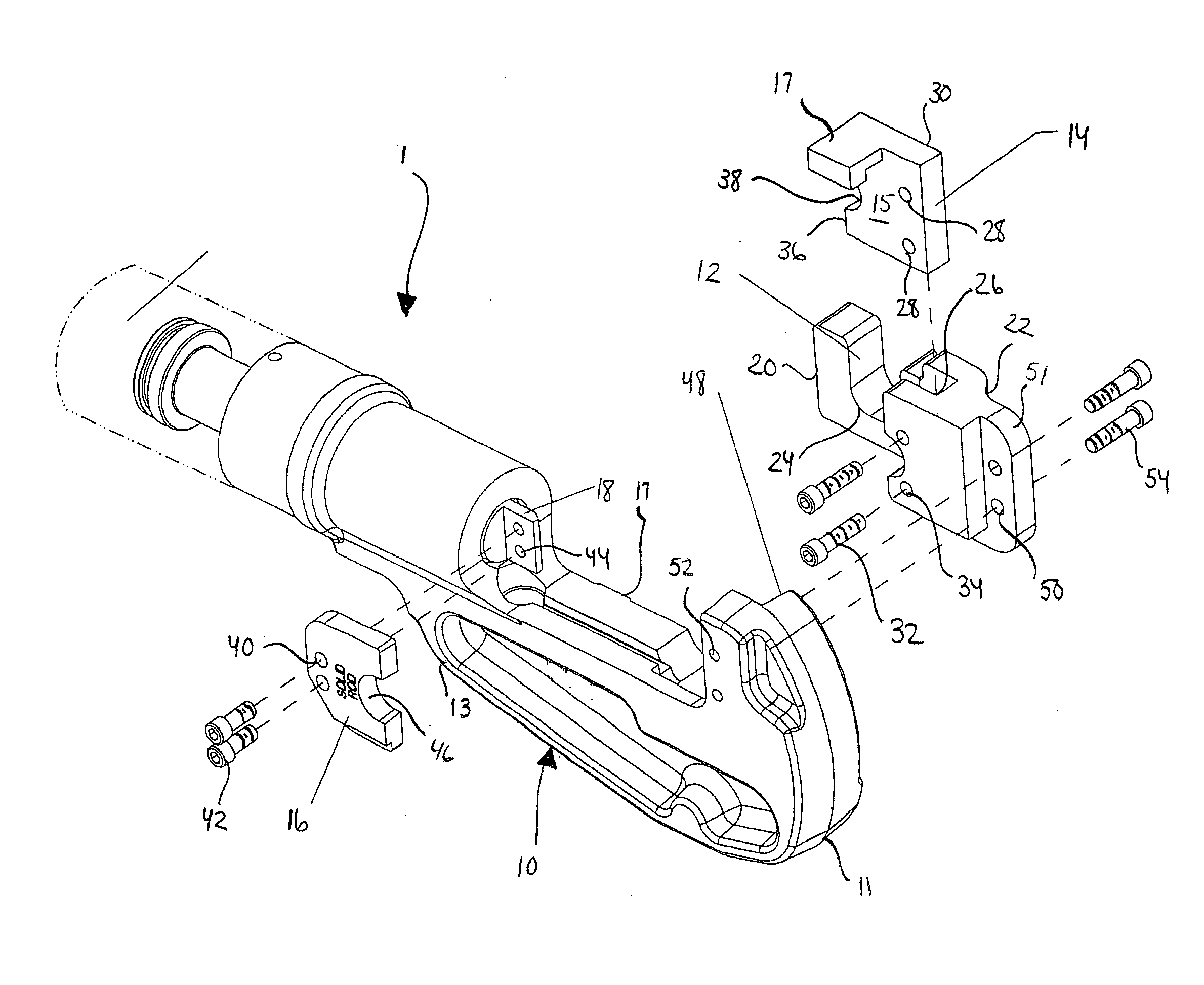
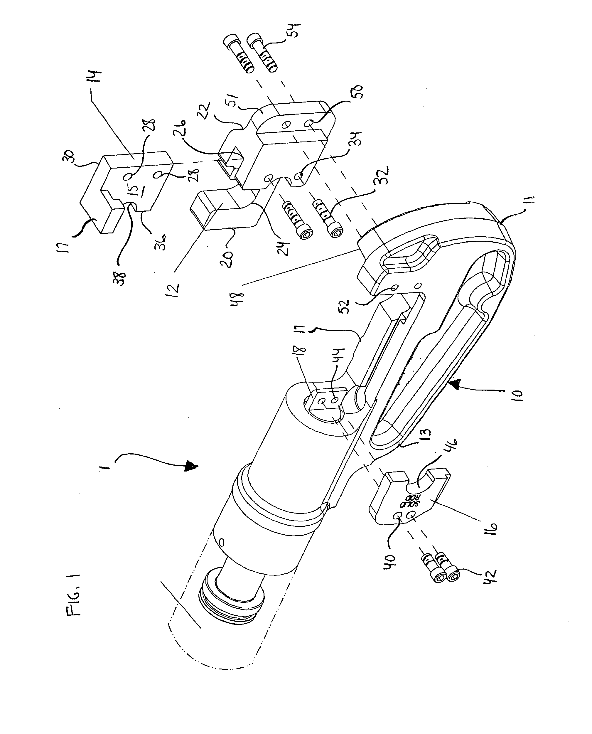
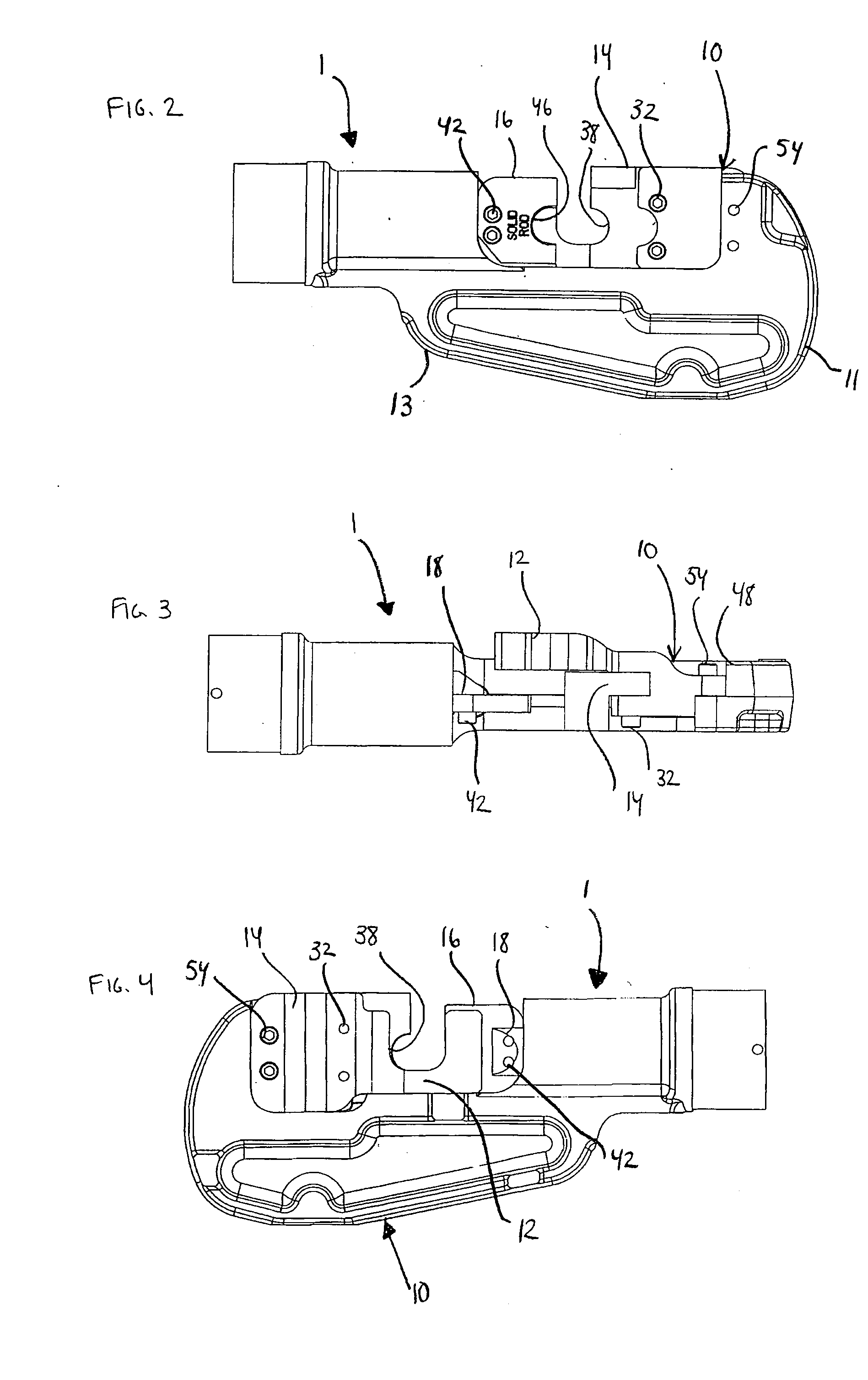
[0024]As seen in FIG. 1, a hydraulic cutting tool 1 includes a generally C-shaped tool head 10 with a blade holder 12 attached thereto. The tool head 10 includes a first end 11 adjacent the blade holder 12 and an opposing second end 13 adjacent a power actuator, such as a hydraulically powered ram 18. A receiving area 17 for the blade holder 12 extends along the longitudinal axis of the cutting tool 1 between the first end 11 and the second end 13. A fixed blade 14 is attached to the blade holder 12 adjacent the first end 11. A moving blade 16 is attached to the hydraulically powered ram 18 adjacent the second end 13. The hydraulically powered ram 18 attached to the tool head 10 forces the moving blade 16 towards and away from the fixed blade 14.
[0025]The blade holder 12 is attached to the first end 11 and restrains various types of materials to be cut by the hydraulically cutting tool 1. The blade holder 12 includes a first end 20 and a second end 22. The first end 20 is defined by...
PUM
 Abstract
Description
Claims
Application Information
 - R&D
- Intellectual Property
- Life Sciences
- Materials
- Tech Scout
- Unparalleled Data Quality
- Higher Quality Content
- 60% Fewer Hallucinations
Browse by: Latest US Patents, China's latest patents, Technical Efficacy Thesaurus, Application Domain, Technology Topic, Popular Technical Reports.
© 2025 PatSnap. All rights reserved.Legal|Privacy policy|Modern Slavery Act Transparency Statement|Sitemap|About US| Contact US: help@patsnap.com


