Wave Energy Converter

a wave energy converter and wave energy technology, applied in the direction of positive displacement liquid engine, pump, machine/engine, etc., can solve the problems of increasing capital cost, reducing reliability, and few of such devices are actually under sustained commercial development, so as to prevent fluctuations in such movement

Inactive Publication Date: 2007-11-01
SEAPOWER PACIFIC
View PDF1 Cites 14 Cited by
  • Summary
  • Abstract
  • Description
  • Claims
  • Application Information

AI Technical Summary

Benefits of technology

[0014] Pumps acting in opposition may serve to provide hydraulic resistance to movement of the diaphragm in both directions, thereby dampening fl

Problems solved by technology

There have been many proposals for devices that seek to harness ocean wave energy but only a few of such devices are actually under sustained commercial development.
The net result is increased

Method used


Image

  • Wave Energy Converter
  • Wave Energy Converter
  • Wave Energy Converter

Examples


first embodiment

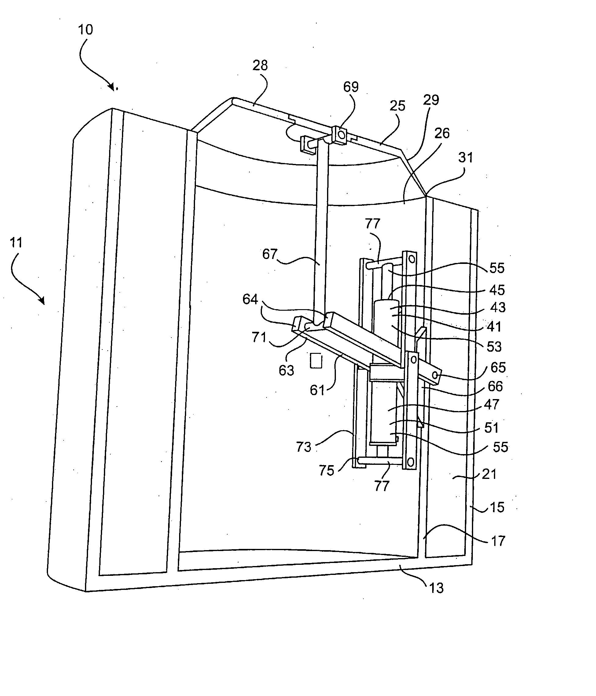
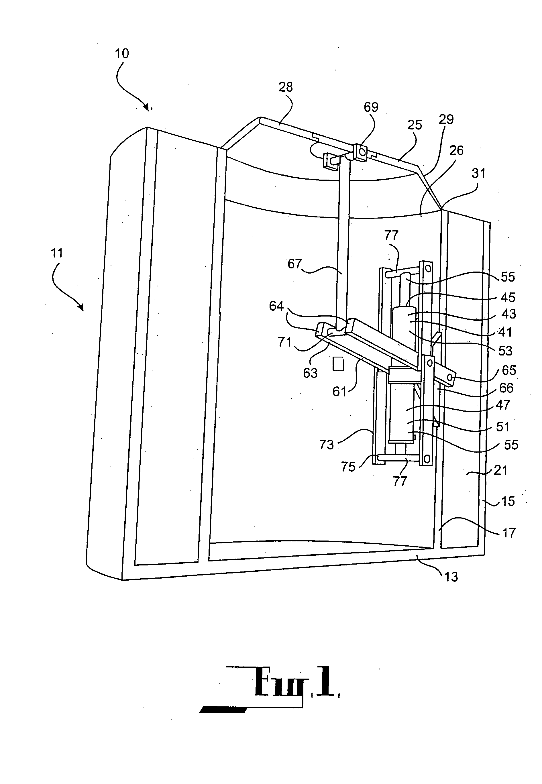
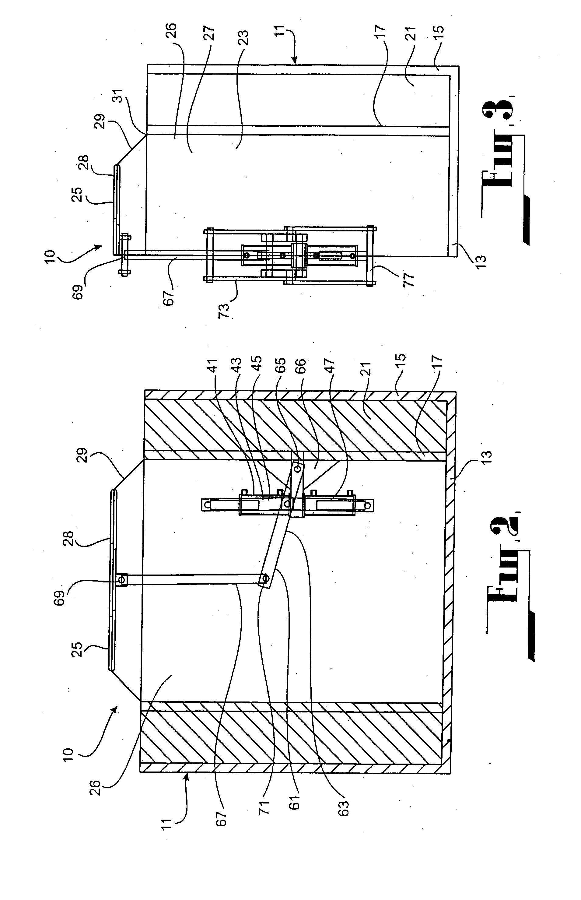
[0076] Referring to FIGS. 1, 2 and 3, there is shown apparatus 10 according to a The apparatus 10 comprises a body structure 11 comprising a base 13 which rests on the seabed, and two walls 15, 17 upstanding from the base. Typically, the base 13 and the two upstanding walls 15, 17 are of integral construction and formed of concrete. Wall 15 is of generally cylindrical construction and provides an outer peripheral wall for the body structure. Wall 17 is also of generally cylindrical construction and is spaced inwardly of wall 15 to provide an inner wall within the body structure.

[0077] The spacing between the outer and inner walls 15, 17 defines a ballast chamber 21 for receiving ballast material. Typically, the ballast material comprises saturated sand taken from the seabed. In this embodiment, the upper end of the ballast chamber 21 is open to receive the ballast material. A closure (not shown) may be provided for closing the ballast chamber 21 if desired.

[0078] The inner cylindr...

second embodiment

[0099] In the apparatus 90 the lever mechanism 61 is guided as it undergoes reciprocating movement in response to movement of the diaphragm 25 under the influence of wave action. The guided movement is provided by way of a guide mechanism 91 comprising a guide structure 93 moveable along a guide 95. In this embodiment, the guide 95 is provided by the inner surface 97 of the cylindrical inner wall 17.

[0100] The guide structure 93 comprises a guide frame 101 attached to the underside of the rigid portion 28 of the diaphragm 25. The guide frame 101 supports guide rollers 103 in rolling engagement with the wall surface 97. The guide frame 101 includes a plurality of circumferentially spaced longitudinal elements 105, each of which carries two of the guide rollers 103 spaced along the longitudinal element.

[0101] Cooperation between the guide structure 93 and the wall surface 97 guides movement of the diaphragm 25 in response to the wave action, ensuring that the diaphragm does not defl...

third embodiment

[0102] Referring now to FIGS. 6 to 9, there is shown apparatus 110 according to a The apparatus 110 comprises a body structure 111 of generally rectangular construction, having a base 113 which rests on the seabed, two opposed side walls 115, two opposed end walls 117, and a top wall 119.

[0103] Two cylindrical inner walls 121, 122 are provided within the body structure 111 between the base 113 and the top wall 119.

[0104] Each cylindrical inner wall 121, 122 is closed at the bottom by the base 113 and opens onto the top wall 119 to define an opening 127 which is closed by a respective diaphragm 129. With this arrangement, the base 113, the inner walls 121, 122 and the diaphragms 129 cooperate to form two cells 130 each defining a working chamber 123.

[0105] Each diaphragm 129 comprises a rigid central portion 131 and a flexible outer portion 133 surrounding the central portion. The outer periphery of each diaphragm 129 is sealingly connected to the upper periphery of its respective...


PUM


Abstract

Apparatus (10) rests on the seabed at a location below sea level for capturing wave energy. The apparatus (10) comprises a body structure (11) having a diaphragm (25) adapted to deflect in response to wave action. A working chamber (27) is disposed immediately below the diaphragm (25) and contains a compressible fluid such as air. A pump system (43) is accommodated within the working chamber (27). The pump system (43) comprises two reciprocating pumps (45, 47) operating in opposition. The pumps (45, 47) are operably connected to the diaphragm (25) through a lever mechanism (61). Because of the geometry of the lever mechanism (61), the stroke length of each pump (45, 47) is less than the amplitude of displacement of the diaphragm (25) as it moves in response to wave action. Thus, the lever mechanism (61) increases the force acting on each pump (45, 47) by a given ratio and reduces the stroke of each pump by the same ratio. The reduction in stroke length provides for compact construction so that the pumps (45, 47) can be readily accommodated within the working chamber (27). The pumps (45, 47) draw seawater from the environment about the apparatus (10) and discharge the seawater at a high-pressure. The high-pressure seawater generated by the pumps can be piped to shore for use in any appropriate purpose.

Description

FIELD OF THE INVENTION [0001] This invention relates to apparatus for converting wave energy in a body of water into a form which can perform useful work. [0002] The invention has been devised particularly, although not necessarily solely, for harnessing wave energy and converting the harnessed energy to pressurised fluid for use in any appropriate way. The fluid may comprise water drawn from the body of water itself. Where the body of water comprises an ocean, seawater drawn from the ocean may be piped under high-pressure to shore and fed to a reverse osmosis desalination unit to yield fresh water. The salt water concentrate exiting the desalination unit, which is still at high-pressure, may be fed to a turbine and the shaft power used to generate electricity. BACKGROUND ART [0003] There have been many proposals for devices that seek to harness ocean wave energy but only a few of such devices are actually under sustained commercial development. All of the commercial devices, whethe...

Claims


Application Information

Patent Timeline
IPC IPC(8): F04B35/00F03B13/18
CPCF03B13/148Y02E10/38F03B13/1815Y02A20/144Y02E10/30F03B13/18
Inventor BURNS, ALAN ROBERT
Owner SEAPOWER PACIFIC
Why Eureka
Try Eureka