Squatting pan and squatting pan flushing system

A squatting toilet and flushing technology, applied in the field of bathroom, can solve the problems of reduced drainage speed and large drainage noise, and achieve the effects of saving stroke, reducing noise and improving flushing effect.

Pending Publication Date: 2020-07-14
谷力(厦门)科技有限公司
View PDF0 Cites 1 Cited by
  • Summary
  • Abstract
  • Description
  • Claims
  • Application Information

AI Technical Summary

Problems solved by technology

[0003] In view of the above problems, the object of the present invention is to provide a squatting pan and a squatting pan flushing system, which solves the problem o

Method used


Image

  • Squatting pan and squatting pan flushing system
  • Squatting pan and squatting pan flushing system
  • Squatting pan and squatting pan flushing system

Examples


Example Embodiment

[0028] Example one

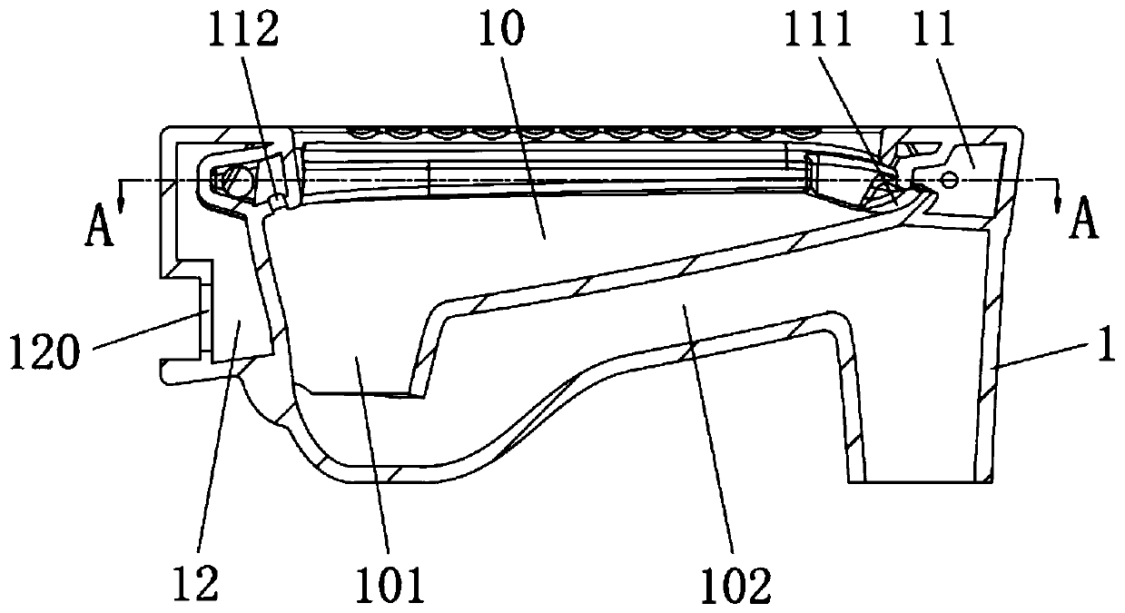
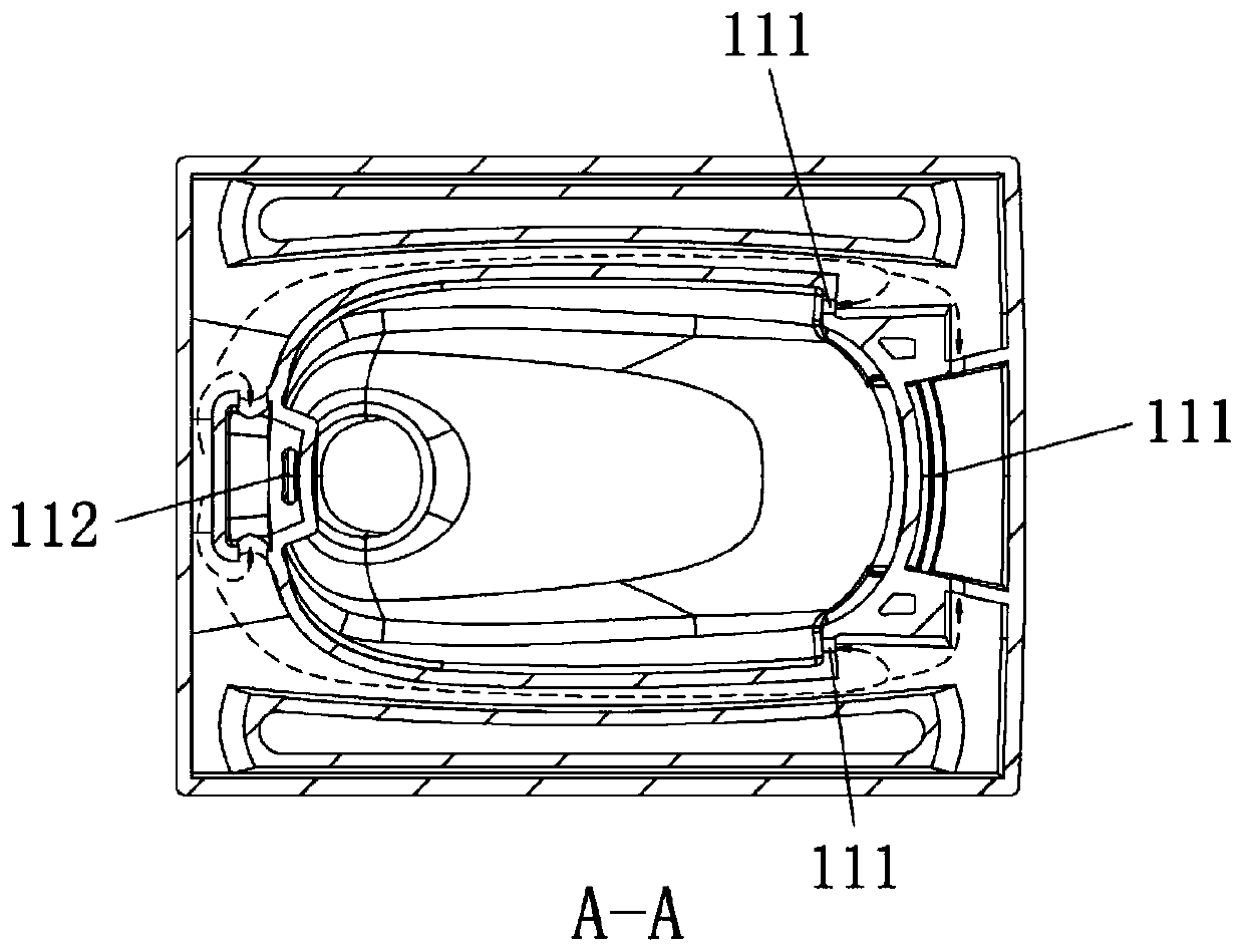
[0029] Such as figure 2 , image 3 As shown, a squatting pan includes a squatting pan ceramic body 1. The top of the squatting pan ceramic body 1 is provided with a toilet 10, the bottom of the toilet 10 is provided with a submerged bay 101, and the submerged bay 101 is connected with a sewage siphon 102. An annular flushing pipe 11 is provided around the top of the bowl 10 along the edge, and flushing hole groups are opened on the wall of the annular flushing pipe 11. The flushing hole group includes one or more first flushing holes 111 for flushing the peripheral wall of the toilet bowl 10 and one or more second flushing holes 112 for flushing the submerged bay 101. The first flushing hole 111 is provided on the side of the annular flushing pipe 11 and facing the peripheral wall of the toilet 10, and the second flushing hole 112 is provided on the bottom of the annular flushing pipe 11 and facing the submerged bay 101.

[0030] The inside of the squatting p...

Example Embodiment

[0034] Example two

[0035] Such as Image 6 , Figure 7 As shown, the difference between this embodiment and the first embodiment is only: the position of the water inlet 120 is higher than the position of the flushing hole group, and there is a fixed piece inside the water storage bay 12 for separating the water inlet 120 and the annular flushing pipe 11 Baffle 121 on both sides. The top of the water baffle 121 is in sealed connection with the top wall surface of the water storage bay 12, and the bottom is provided with a water gap 122 for connecting the water inlet 120 and the annular flushing pipe 11, and the position of the bottom end of the water baffle 12 is lower than the position of the flush hole group . The rest of the structure and principle of this embodiment are the same as the first embodiment.

Example Embodiment

[0036] Example three

[0037] Such as Figure 8-10 As shown, the difference between this embodiment and the first embodiment is that the water storage space is an S-shaped conveying pipe 13, and the position of the water inlet 120 is lower than the position of the flushing hole group. The bottom inlet of the S-shaped conveying pipe 13 is connected to the water inlet 120, and the top outlet faces the annular flushing pipe 11 and is located lower than the annular flushing pipe 11. The end face of the top outlet side of the S-shaped conveying pipe 13 is inclined to the right and downward and forms an obtuse angle α of 120-145° with the horizontal plane. The rest of the structure of this embodiment is the same as the first embodiment.

[0038] The working principle of this embodiment is: in a normal water stop state, the overflow device 6 isolates the outside air and communicates with the drain port of the drain valve 4 base through the overflow pipe 5. The water stored in the S-sha...


PUM


Abstract

The invention discloses a squatting pan which comprises a squatting pan ceramic body, a urinal is arranged at the top of the squatting pan ceramic body, a water sinking bay is arranged at the bottom of the urinal, and the water sinking bay is connected with a blowdown siphon. An annular flushing pipeline is arranged at the top of the urinal, and a flushing hole set is formed in the wall face of the annular flushing pipeline. A water storage space used for preventing external air from entering the water tank drainage pipe from the annular flushing pipeline is formed in the squatting pan ceramicbody, and the bottom of the water storage space is lower than the annular flushing pipeline. The upper portion of the water storage space is communicated with the annular flushing pipeline, and a water inlet used for being connected with a drainage pipe is formed in the side wall of the water storage space. The invention further discloses a squatting pan flushing system comprising the squatting pan. External air is prevented from entering the water tank drainage pipe from the annular flushing pipeline through the water storage space, noise generated when the water tank works is greatly reduced, water capable of directly acting on next flushing can be pre-stored in the water tank drainage pipe after each time of flushing, the stroke of water is saved, and the flushing effect is good.

Description

technical field [0001] The invention relates to the field of sanitary ware, in particular to a squatting pan and a squatting pan flushing system. Background technique [0002] Existing squatting toilet flushing systems such as figure 1 As shown, in the normal water-stop state, the outside air communicates with the outlet 1002 of the drain valve base through the overflow pipe 1001 , and the outside air communicates with the outlet 1004 of the drain pipe through the ceramic water channel 1003 . When the drain valve is opened, water flows out through the drain port 1002 of the valve base. During normal use, since the drain port 1002 of the valve base communicates with the outside air through the overflow channel, when draining, a negative pressure will be generated in the drain channel 1005, and the external Under the action of atmospheric pressure, air will be mixed into the drain port 1002 of the valve base together, so that the drain channel 1005 cannot store water, thereby...

Claims


Application Information

Patent Timeline
IPC IPC(8): E03D11/04E03D11/13E03D11/18E03D11/17E03D1/00E03D1/34E03D1/38E03D9/14
CPCE03D1/00E03D1/34E03D1/38E03D9/14E03D11/04E03D11/13E03D11/17E03D11/18Y02A20/40
Inventor 陈雪瑜
Owner 谷力(厦门)科技有限公司
Why Eureka
Try Eureka