
Systems and methods for providing illumination in machine vision systems

a machine vision and system technology, applied in the field of machine vision systems, can solve the problems of color systems that require more computations per second, not necessarily difficult inspection operations, and product defects,

Inactive Publication Date: 2006-05-09
SIGNIFY NORTH AMERICA CORP
View PDF200 Cites 207 Cited by
  • Summary
  • Abstract
  • Description
  • Claims
  • Application Information

AI Technical Summary

Benefits of technology

The LED lighting system provides high-energy output across the visible spectrum, enabling fast and precise lighting adjustments to improve image recognition, reduce false indications, and enhance the effectiveness of machine vision systems, especially in high-speed production environments.

Problems solved by technology

Many manufacturing and inspection operations are not necessarily difficult but they are boring.
It is the boredom of these tasks that causes people to become unfocused during the operation, leading to defects in the product.
These color systems require more computations per second because of the complexity of the system.
Many of these systems work on high-speed productions lines where any reduction in speed is intolerable, necessitating the need for increased computational power.
If the lighting does not create the proper contrast or color, the system will slow down, give false indications, or completely fail to operate.
This low contrast can lead to false readings or false indications.
These light sources typically do not provide equal amounts of energy throughout the visible spectrum but they do emit some energy throughout most of the spectrum.
Fluorescent lamps tend to have gaps in the spectral output where there may be little or no emission.

Method used


Image

  • Systems and methods for providing illumination in machine vision systems
  • Systems and methods for providing illumination in machine vision systems
  • Systems and methods for providing illumination in machine vision systems

Examples


Embodiment Construction

)

[0019]The description below pertains to several illustrative embodiments of the invention. These are described merely for illustrative purposes, as the scope of the invention is not to be limited in any way by the disclosure below.

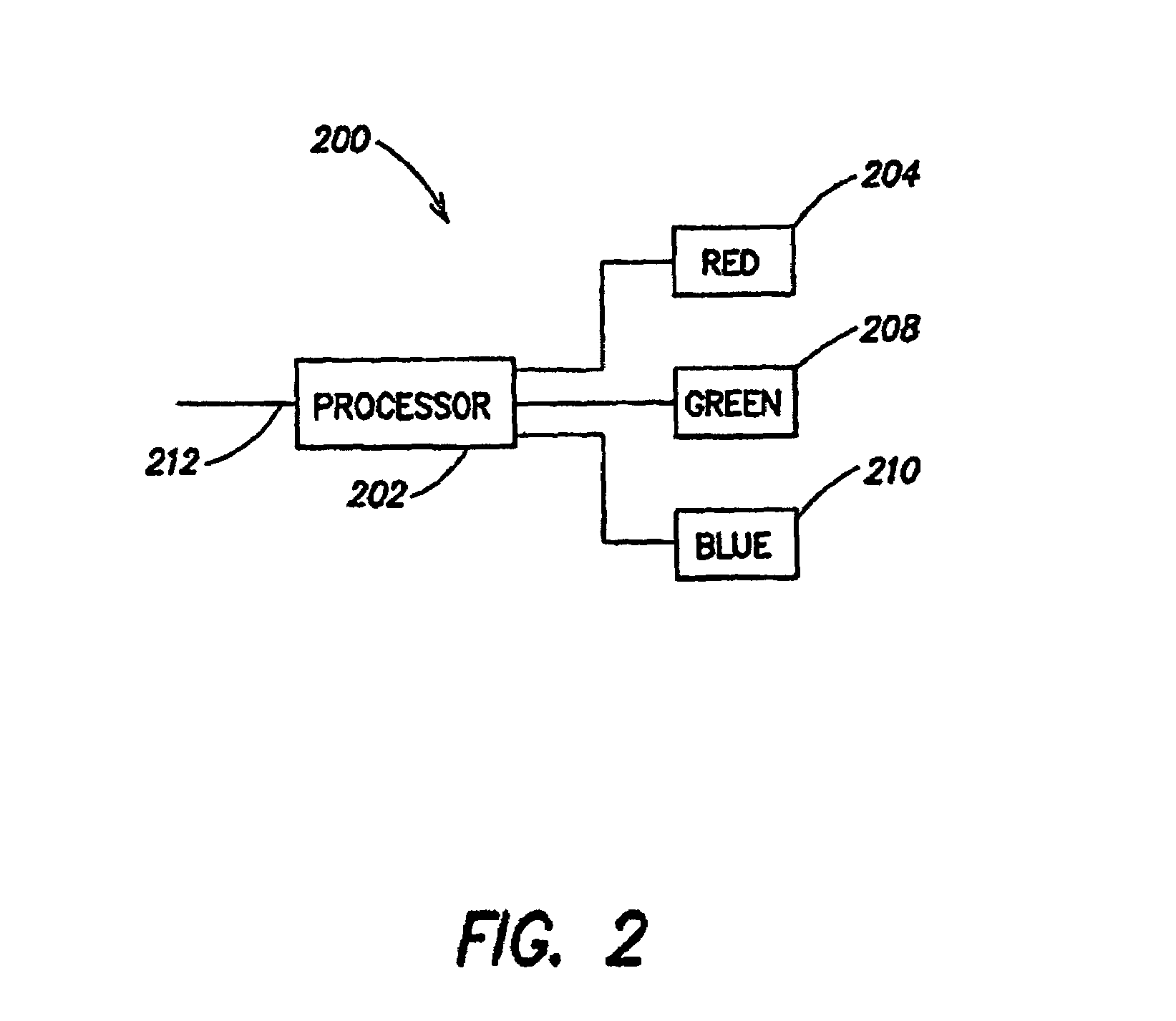
[0020]The development of high brightness LEDs and the development of digital lighting technology has created many opportunities for LED lighting. U.S. Pat. Nos. 6,016,038 and 6,211,626 describe many such lighting devices. U.S. Pat. Nos. 6,016,038 and 6,211,626 are hereby incorporated by reference herein. These patents describe methods of controlling the light output from a lighting system comprised of different colored LEDs for example. Embodiments of these patents describe the use of pulse width modulation (PWM) and independent control of the LEDs to produce varying color within a color spectrum.

[0021]In one embodiment of the present invention, an LED lighting device with color changing capabilities may be used to illuminate objects in a vision system or...


PUM

PropertyMeasurementUnit
spectrumaaaaaaaaaa
pulse widthaaaaaaaaaa
pulse displacementaaaaaaaaaa

Abstract

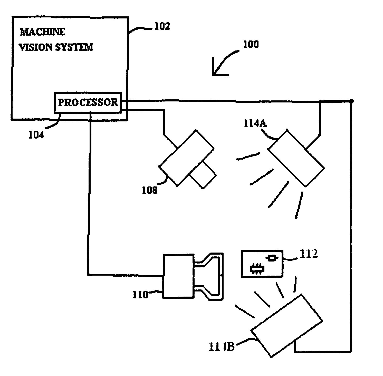
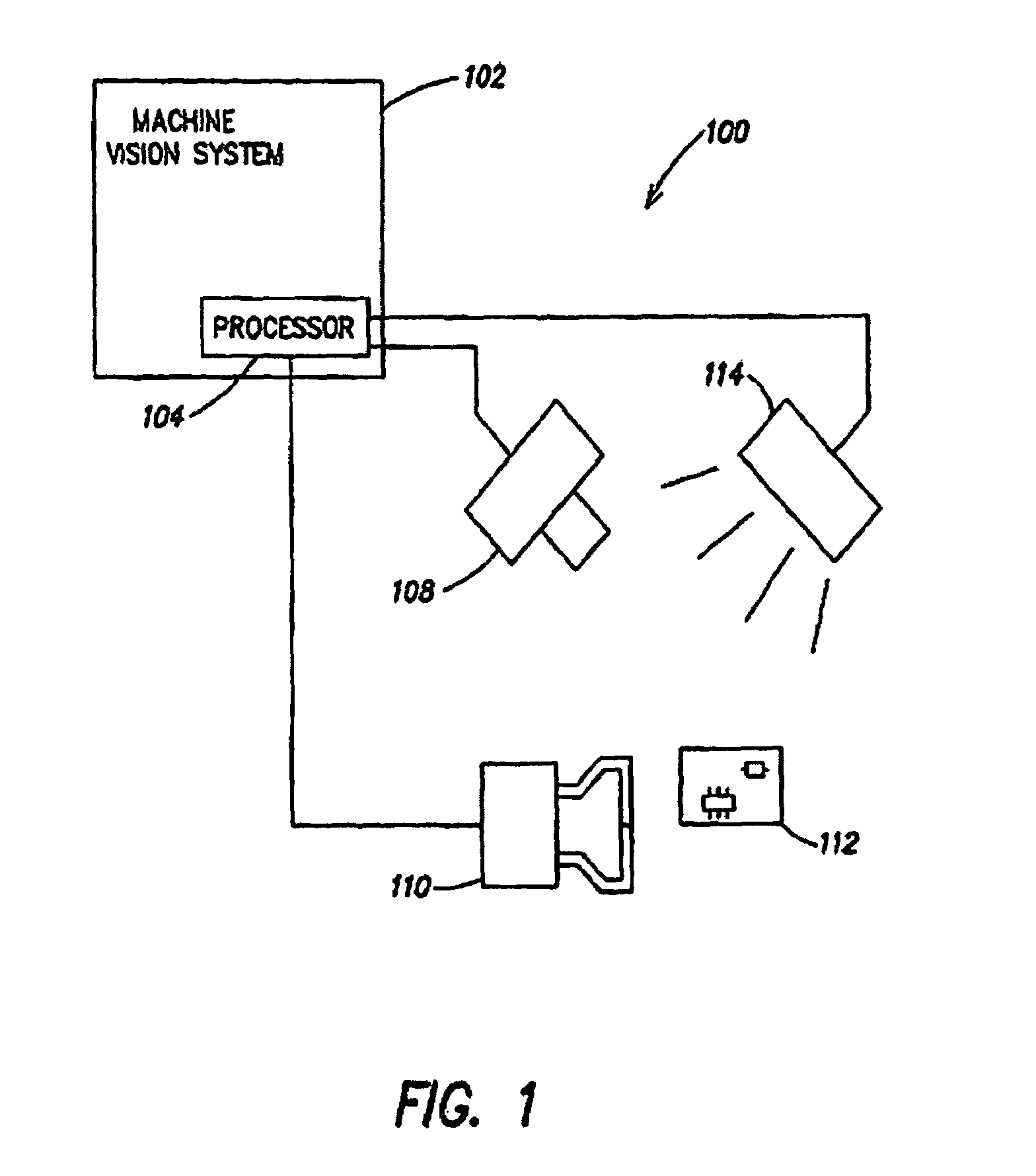
A lighting system associated with a machine vision system. The machine vision system may direct lighting control commands to the lighting system to change the illumination conditions provided to an object. A vision system may also be provided and associated with the machine vision system such that the vision system views and captures an image(s) of the object when lit by the lighting system. The machine vision system may direct the lighting system to change the illumination conditions and then capture the image.

Description

CROSS-REFERENCES TO RELATED APPLICATIONS[0001]This Application claims the benefit, under 35 U.S.C. §120, as a continuation (CON) of U.S. Non-provisional application Ser. No. 09 / 944,523, filed Aug. 31, 2001 now U.S. Pat. No. 6,624,597, entitled “Systems and Methods for Providing Illumination in Machine Vision Systems,” which application in turn claims priority to U.S. Provisional Application Serial No. 60 / 229,849, filed Sep. 1, 2000, entitled “Machine Vision.” Each of the foregoing applications is hereby incorporated herein by reference.BACKGROUND OF THE INVENTION[0002]1. Field of the Invention[0003]The invention relates to machine vision systems. More particularly, this invention relates to lighting systems for machine vision systems.[0004]2. Description of Related Art[0005]Machine vision systems have been in use for many years. These systems are designed to remove the human element from the manufacturing and inspection process. Many manufacturing and inspection operations are not n...

Claims


Application Information

Patent Timeline
Patent Type & Authority Patents(United States)
IPC IPC(8): G05F1/00G01N21/88
CPCG01N21/8806
Inventor DOWLING, KEVIN J.MUELLER, GEORGE G.LYS, IHOR A.
Owner SIGNIFY NORTH AMERICA CORP
Learn More