Method and device for perception of an object by its shape, its size and/or its orientation

a technology of object shape and orientation, applied in the field of automatic visual perception, can solve the problem of inability to isolate a number of points greater than the fixed threshold, and achieve the effect of reducing the number of points

Inactive Publication Date: 2006-05-09
HLDG B E V +1
View PDF32 Cites 94 Cited by
  • Summary
  • Abstract
  • Description
  • Claims
  • Application Information

AI Technical Summary

Benefits of technology

[0018]the position of the center of gravity of the points making up a region of interest are stored in an associated memory thereby enabling its identification,

Problems solved by technology

Conversely, when processing a space at a given instant, or still frame, isolation of a number of points greater than the fixed threshold is generally not possible.

Method used


Image

  • Method and device for perception of an object by its shape, its size and/or its orientation
  • Method and device for perception of an object by its shape, its size and/or its orientation
  • Method and device for perception of an object by its shape, its size and/or its orientation

Examples


first embodiment

[0154]A. First Embodiment of Classifier

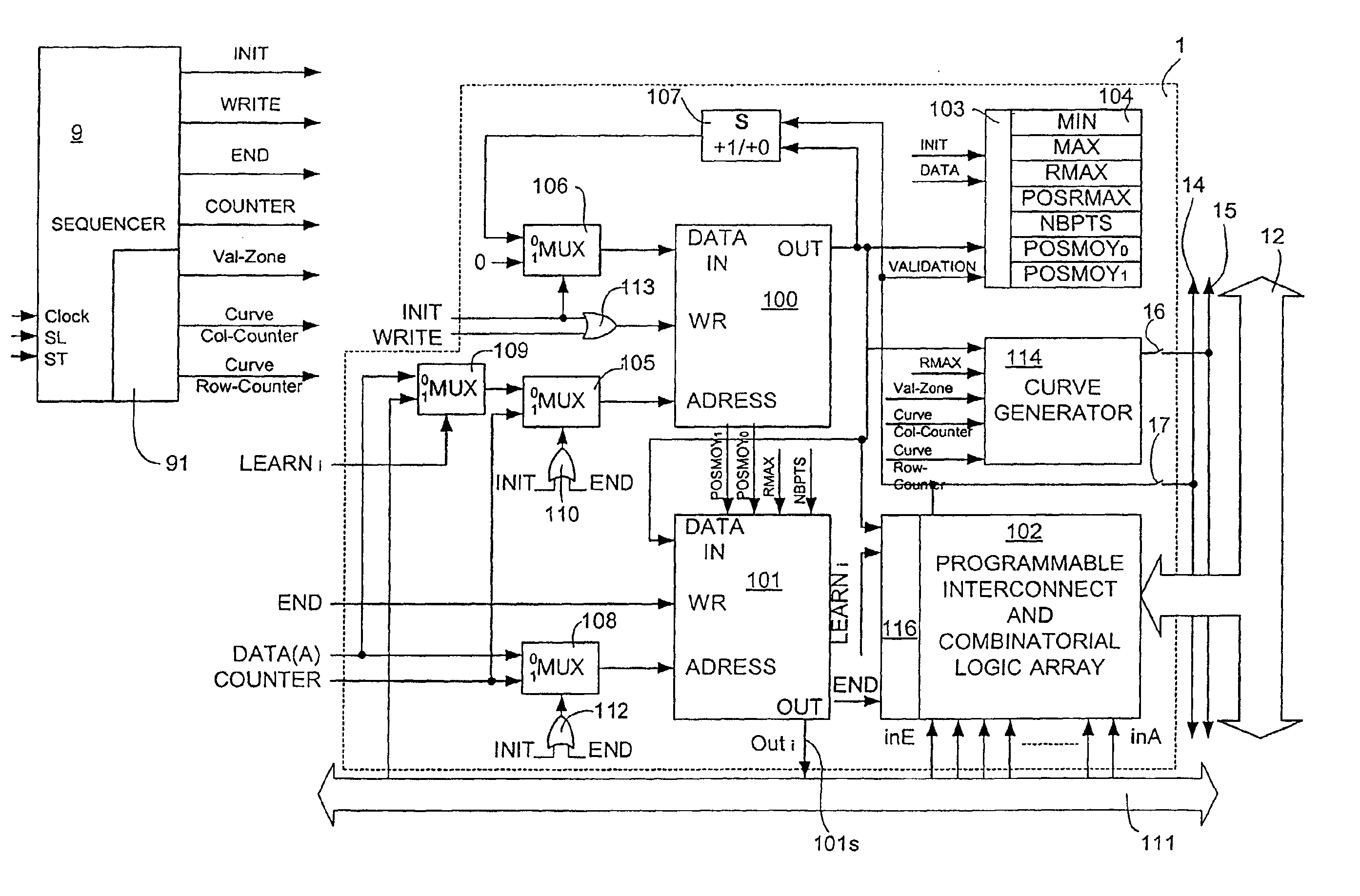
[0155]With reference to FIG. 12, the classifier 101 fulfilling the self-adapting function comprises a memory 118 whose writing input terminal WR receives the signal END and the address input terminal ADDRESS receives the output signal of the address multiplexer 108.

[0156]Classifier 101 also includes a comparator 119 comprising two inputs and one output that is connected to the data input DATA IN of the memory 118.

[0157]The first input, Q, of the comparator 119 receives a value derived from an analysis output register 104 and its second input receives the output of the memory 100. In one embodiment, for example, the value received at the first input Q is the value RMAX / 2, derived from RMAX register 104 in conjunction with divider circuit 121.

[0158]Memory 118 of the classifier 101 preferably comprises the same number of words as the analysis memory 100, but in the memory 118, each word comprises one bit only.

[0159]At the end (e.g., signal END=1) ...

second embodiment

[0161]B. Second Embodiment of Classifier

[0162]FIG. 13 represents an alternative embodiment of the classifier 101 including a multiplexer 120 that is controlled by a selection control signal 124. Classifier 101 enables comparison of the parameter P to a statistical value Q, which can be prepared in various ways in relation to the statistical parameters received on the different inputs 0, 1, 2, 3 of multiplexer 120, which are selected by the selection control signal 124, which depends on the content of the register ‘SELECTION’. The input 0 of the multiplexer 120 receives the value RMAX / 2 produced on the basis of the data in the analysis output register 104 by the divider circuit 121, the input 1 of the multiplexer 120 receives directly the value RMAX, the input 2 of the multiplexer 120 receives a threshold value contained in a register ‘THRESHOLD’123 whose content is programmed outside the system, and the input 3 of multiplexer 120 receives the quotient of the number of points NBPTS b...

third embodiment

[0165]C. Third Embodiment of Classifier

[0166]FIGS. 13a, 13b, 13c represents another embodiment of a classifier in which the cumulative total of events is used in a histogram instead of the levels. The classification boundaries are defined, for example, by the use of a register RMAX, corresponding to a maximum of events for the analyzed parameter, and in searching for the parameter values for RMAX / 2. On both sides of the RMAX position, these values correspond to limit A and limit B of the classifier.

[0167]Hence, the RMAX register such as it is operated in the second embodiment of the classifier, is replaced here by the register NBPTS, corresponding to the total cumulative result of events (FIG. 13a). By removing a percentage k of NBPTS on both sides of the histogram, the limits A and B become more stable (FIG. 13b).

[0168]The device represented in FIG. 13c carries out this function.

[0169]In FIG. 13c, the analysis memory 100 and the command of the address multiplexer 105 are present. T...


PUM


Abstract

Systems and methods for localizing a shape in a space represented by pixel data forming a multidimensional space i, j, evolving with time, and represented at a succession of instants T, wherein the data is associated with a temporal parameter A, B, . . . in the form of digital signals DATA(A), DATA(B), . . . composed of a sequence Aijt, Bijt, . . . of binary numbers of n bits associated with synchronization signals defining the instant T of the space and the position i, j in this space, at which the signals Aijt, Bijt, . . . were received. In one embodiment, a) a region of interest of the space is perceived in relation to a statistic criterion applied to a temporal parameter, b) the main region thus perceived is deactivated, c) repeating a) and b) in order to perceive other regions of interest inside a non-deactivated space region, d) the procedure is stopped when a remaining region, non-deactivated, in the space does not provide a region of interest corresponding to the statistic criterion, e) a counter is incremented for each consecutive valid frame for each region of interest thus perceived, and f) for each region of interest thus perceived, the center of gravity is stored.

Description

CROSS-REFERENCES TO RELATED APPLICATIONS[0001]This application is a continuation-in-part of, and claims priority from, U.S. patent application Ser. No. 09 / 792,436, entitled “METHOD AND DEVICE FOR AUTOMATIC VISUAL PERCEPTION,” filed Feb. 23, 2001, which is hereby incorporated by reference in its entirety for all purposes. This application also claims priority from French Patent Application No. 01 02539, filed Feb. 23, 2001, which is hereby incorporated by reference in its entirety for all purposes.BACKGROUND OF THE INVENTION[0002]The invention relates generally to methods and devices for automatic visual perception, and more particularly to methods and devices for processing image signals using two or more histogram calculation units to localize one or more objects in an image signal using one or more characteristics an object such as the shape, size and orientation of the object. Such devices can be termed an electronic spatio-temporal neuron, and are particularly useful for image p...

Claims


Application Information

Patent Timeline
Patent Type & Authority Patents(United States)
IPC IPC(8): G06F15/18G06K9/00
CPCG06K9/00228G06V40/161
Inventor PIRIM, PATRICK
Owner HLDG B E V
Why Eureka
Try Eureka