Resettable combination lock

a combination lock and lock technology, applied in the field of resettable combination locks, can solve the problems of user trouble with resetting the lock, the locking plate is relative difficult to be removed from the holding hole, and the reset lock takes a lot of time and labor, so as to prevent the displacement of the locking pla

Inactive Publication Date: 2006-05-16
WANG MEI LI +1
View PDF10 Cites 34 Cited by
  • Summary
  • Abstract
  • Description
  • Claims
  • Application Information

AI Technical Summary

Benefits of technology

[0031]The combination lock of the present invention includes two rows of main buttons projecting out from a front side of an outdoor member, and rotary resetting buttons in an indoor member thereof, which are respectively connected to the main buttons. Each of the main buttons includes an engaging stick formed with first and second trenches, which face opposite directions, and are different distances from a rear end of the stick. The engaging sticks of the buttons are passed through two juxtaposed slots of a plate such that linear displacement of the plate will be p

Problems solved by technology

From the above description, it can be understood that the above conventional lock has the following disadvantages:
1. Because locking plates 50 of the first type are different from the second type in respect of position of the big gaps 501, the user has to relocate the locking plates in the holding holes 105 of the main body 104 with the help of tools in order to change the combination. Therefore, it takes much time and labor to reset the lock.
2. It is relative difficult to remove the locking plates from the holding holes 105, even with pliers, because the holes 105 are narrow. Consequently, the user will get some trouble with resetting the lock.
3. To reset the lock, the user has to first remove the lock member 10 from the door, and separate the rear cover 108 from the housing 101, and remove the springs 107 as well as relocating the locking plates, and finall

Method used


Image

  • Resettable combination lock
  • Resettable combination lock
  • Resettable combination lock

Examples


Embodiment Construction

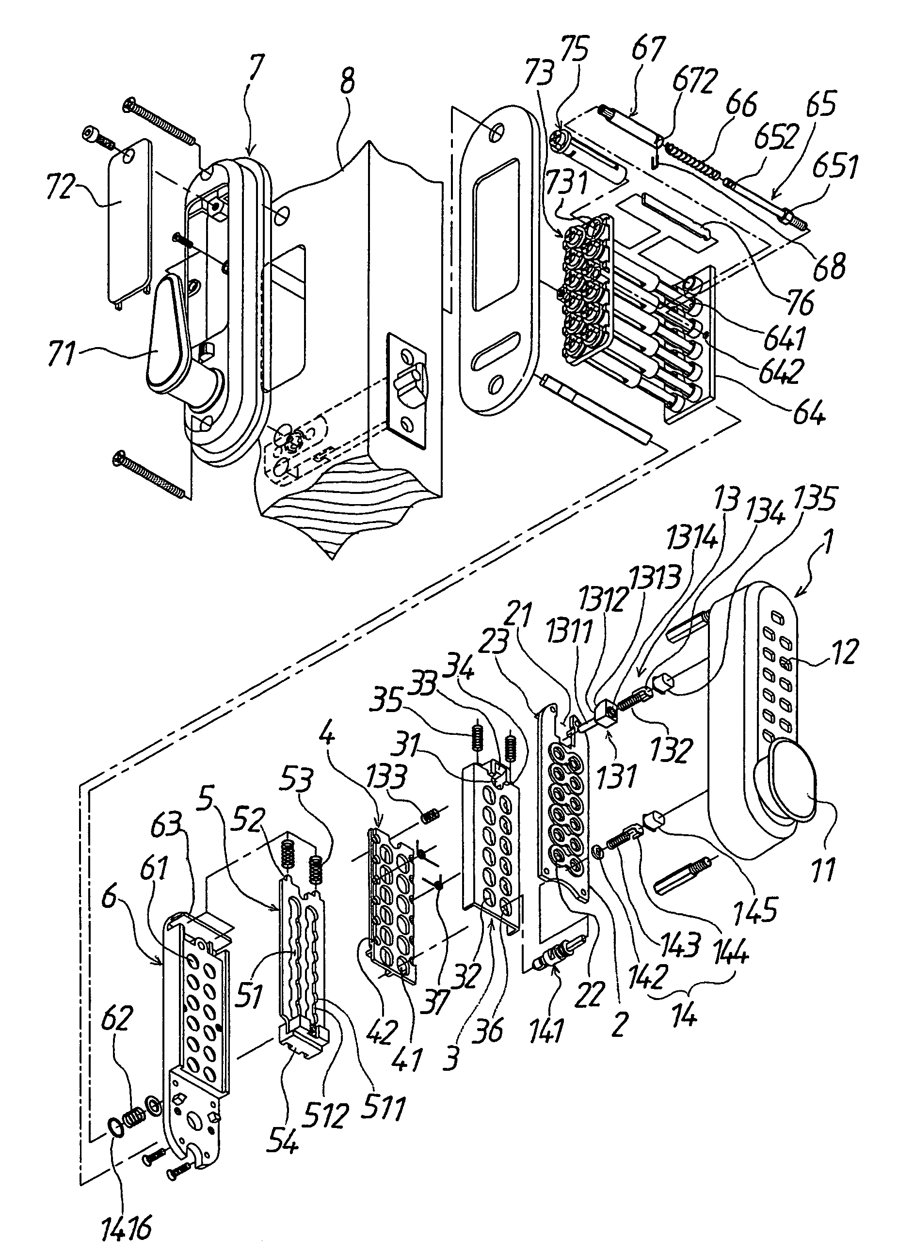
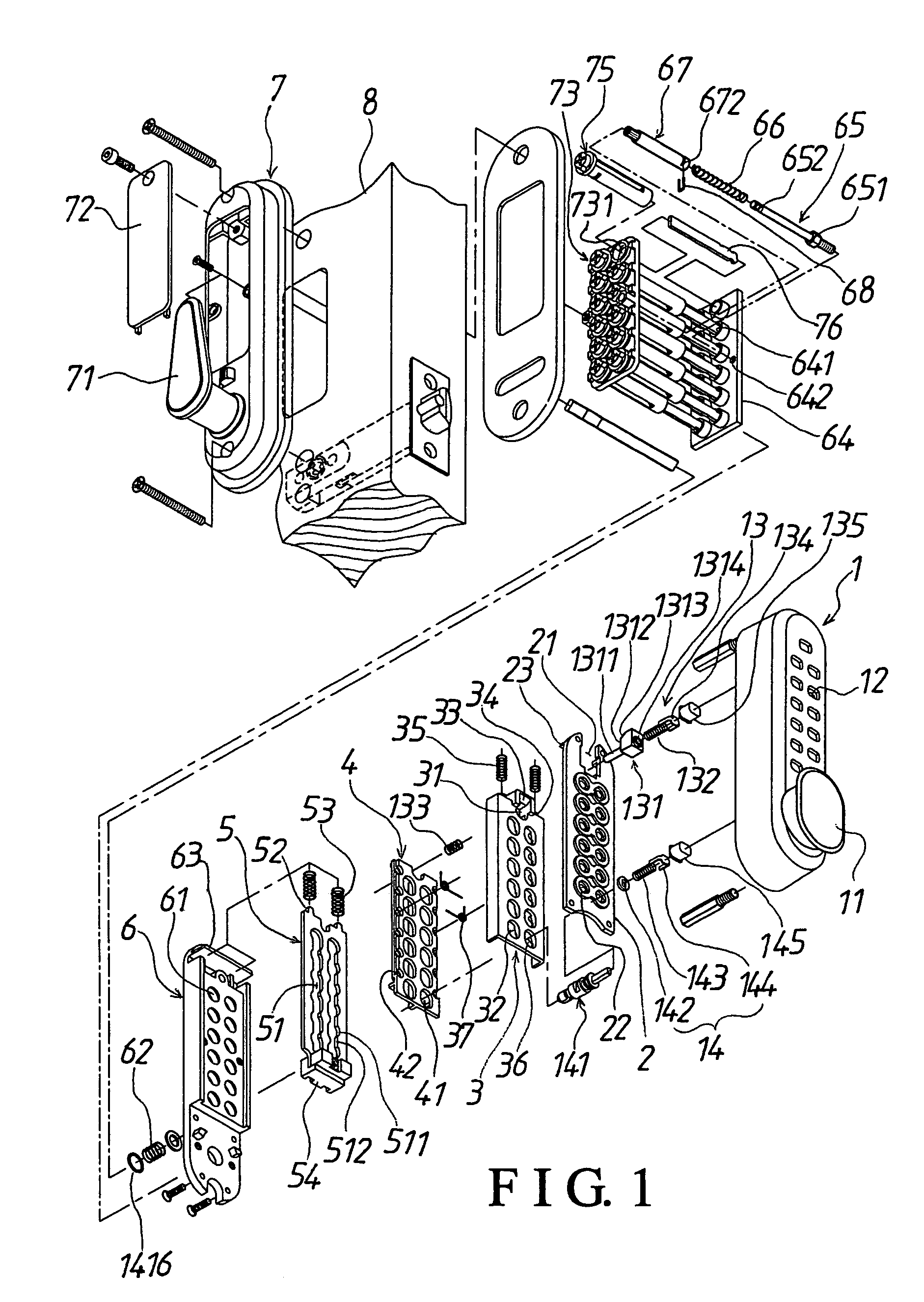
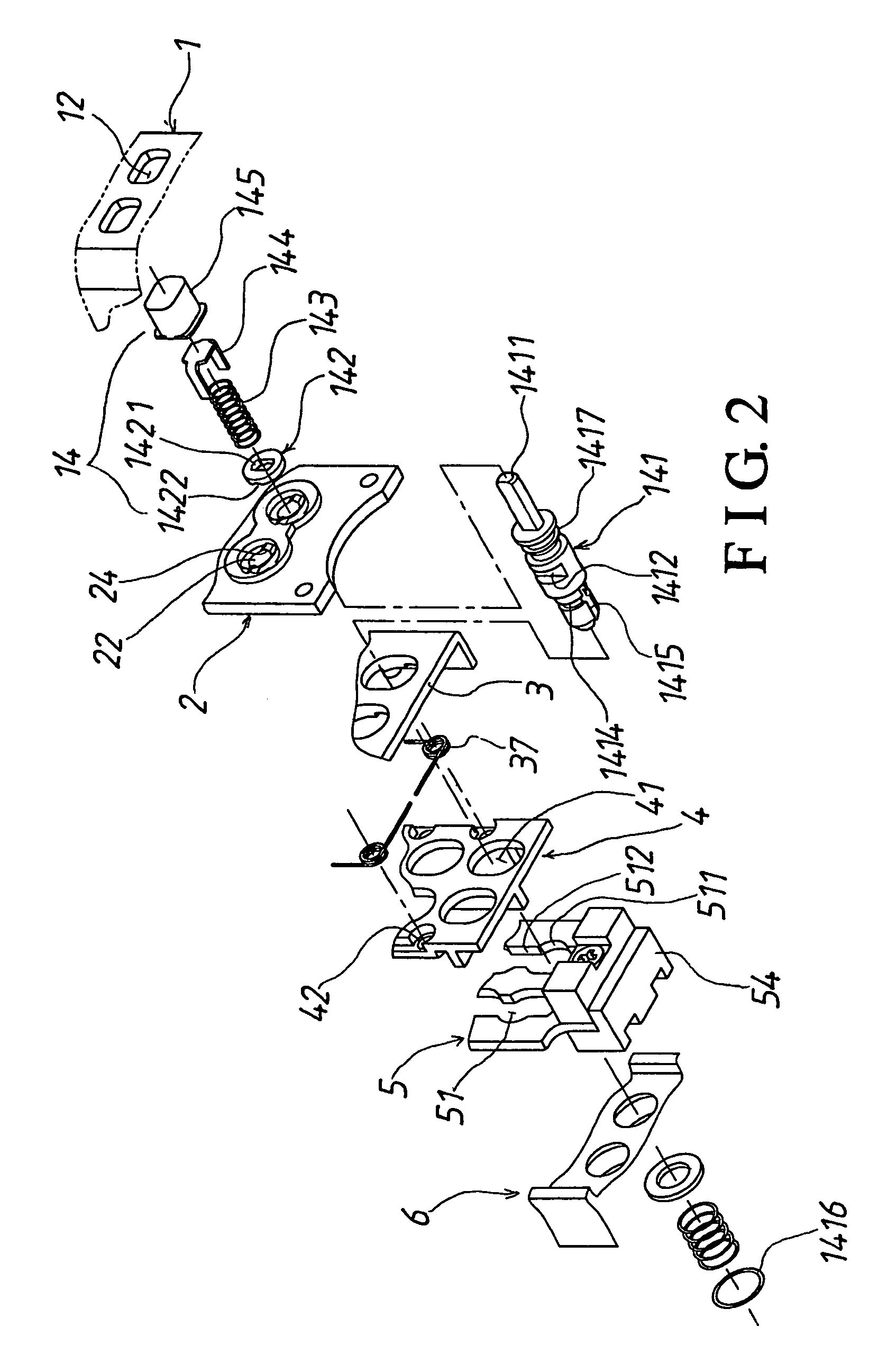
[0050]Referring to FIGS. 1 to 3, a preferred embodiment of a resettable combination lock includes an outdoor member 1 secured on an outer side of a door 8, and an indoor member 7 on an inner side of the door 8.

[0051]The outdoor member 1 includes:

[0052]a housing having a knob 11 connected thereto, and several spaced holes 12 on a front side;

[0053]a restoring button 13 passed through one of the holes 12 of the housing; the restoring button 13 includes a rear pushing post 131, a front spring 132, a rear spring 133, an inner cap 134, and an outer cap 135; referring to FIG. 5 as well, the rear pushing post 131 has a rear post portion 1311, around which the rear spring 133 is passed; the post 131 further has a block portion 1312, which is formed with a slope 1313 on a rear side, and a front recess 1314 holding one end of the front spring 132; the inner cap 134 is fitted on the other end of the front spring 132 while the outer cap 135 is fitted over the inner cap 134, and passes through th...


PUM


Abstract

A resettable combination lock includes two rows of main buttons, and rotary resetting buttons in a rear indoor portion, which are respectively connected to the main buttons for causing angular displacement of the main buttons with; each main button includes a stick formed with first and second trenches, which face opposite directions, and are different distances from a rear end of the stick; the sticks pass through two slots of a plate such that linear displacement of the plate will be prevented when the main buttons are not depressed exactly according to the combination; the lock can be reset in respect of the combination by turning the rotary resetting buttons one hundred and eighty degrees to change the orientation of the trenches of the sticks; the lock is equipped with several telescopic connecting elements therein so as to be adaptable to doors of different thicknesses.

Description

BACKGROUND OF THE INVENTION[0001]1. Field of the Invention[0002]The present invention relates to a resettable combination lock, more particularly one, which can be easily reset, and which can be easily adapted to suit doors of different thicknesses.[0003]2. Brief Description of the Prior Art[0004]Combination locks are convenient to use because they can be unlocked without use of a key, and there won't be risk of losing the key.[0005]Referring to FIGS. 14 to 17, a conventional resettable combination lock includes a lock member 10 secured on an outer side of a door 40, a back cover 20 securely connected to an inner side of the door 40 and the lock member 10, and a knob 30.[0006]The lock member 10 includes:[0007]a housing 101 formed with two rows of spaced holes 102 thereon, which are given respective numbers or symbols;[0008]several buttons 103 held in respective ones of the holes 102 of the housing 101, which includes a restoring button, which can be pressed for making the other butt...

Claims


Application Information

Patent Timeline
IPC IPC(8): E05B13/00
CPCE05B37/16Y10T70/5788Y10T70/722Y10T70/7226Y10T70/739
Inventor WANG, SONG-MING
Owner WANG MEI LI
Why Eureka
Try Eureka