Portable shelter with rolling element bearings

a technology of bearings and folding elements, applied in the field of shelters, can solve the problems of unsightly pockets, reduced tent headroom, unstable folding, etc., and achieve the effect of not reducing tent headroom, compact folding, and easy folding and unfolding

Inactive Publication Date: 2006-05-16
VARIFLEX +1
View PDF76 Cites 30 Cited by
  • Summary
  • Abstract
  • Description
  • Claims
  • Application Information

AI Technical Summary

Benefits of technology

[0013]A general object of the present invention is to provide a collapsible shelter that is superior to those presently known in the art. In particular, one object of the present invention is to provide a shelter frame that is relatively easy to fold and unfold, stable, and still compact when folded. Another object of the present invention is to provi

Problems solved by technology

More specifically, the inventors herein have discovered that the frames associated with prior collapsible shelters tend to be difficult to fold and unfold, unstable, and somewhat large when folded.
Some prior shelter frames also allow the canopy to sag and form unsightly pockets where water can accumulate, reduce tent headroom and/or ultimately produce an unsightly shelter.
The shelter frame shown in FIGS. 7 and 8 is somewhat unstable because the legs A are not directly connected to one another and, instead, are only connected to one another by the structure formed by the scissors-type cross joints B, the center strut C and the connectors E and F. In addition to being unstable, the scissors-type linkage/center strut/connector structure also reduces the headroom within the tent.
This frame is also somewhat difficult to unfold in that an extra person is som

Method used


Image

  • Portable shelter with rolling element bearings
  • Portable shelter with rolling element bearings
  • Portable shelter with rolling element bearings

Examples


Embodiment Construction

[0029]The following is a detailed description of the best presently known mode of carrying out the invention. This description is not to be taken in a limiting sense, but is made merely for the purpose of illustrating the general principles of the invention. The scope of the invention is defined solely by the appended claims.

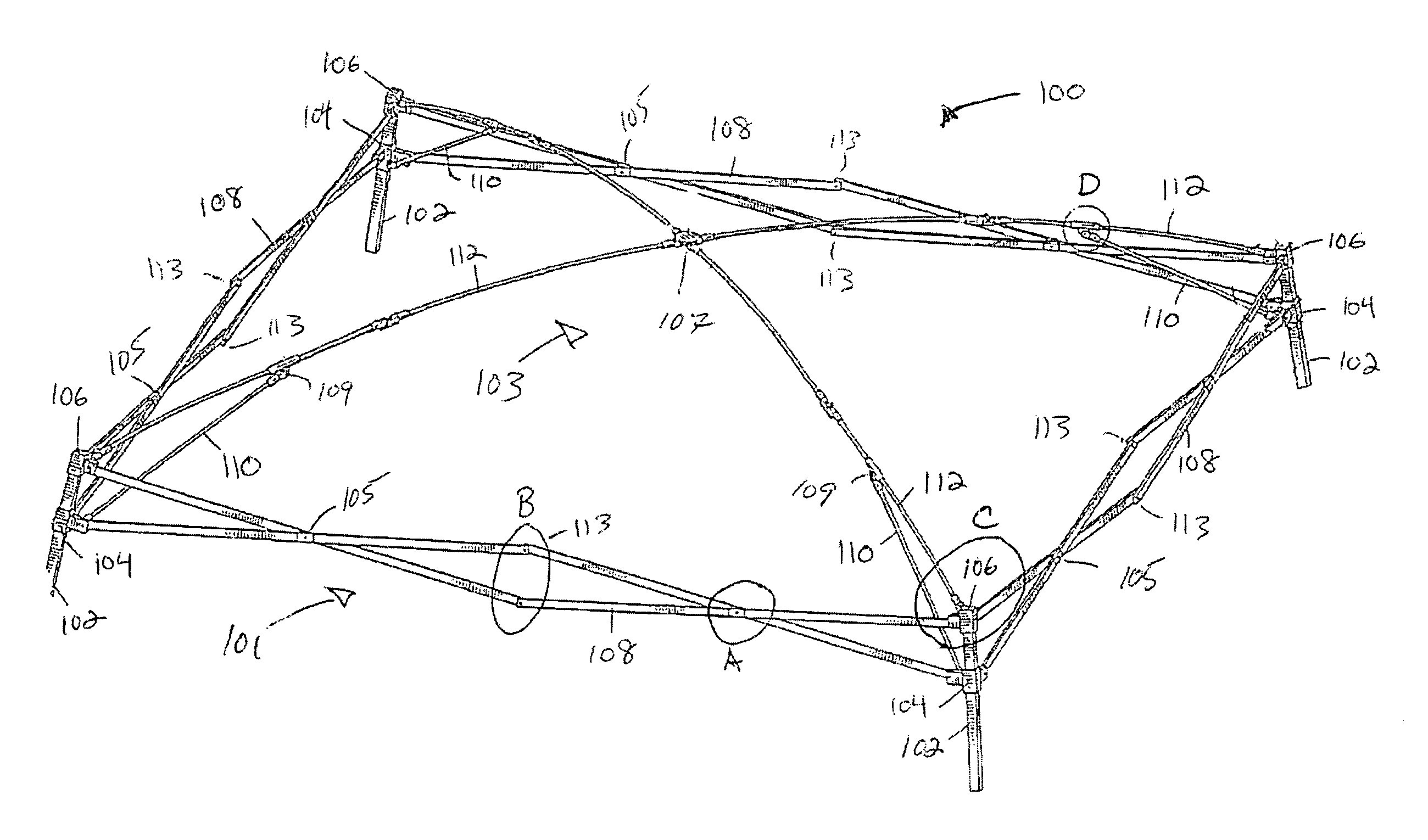
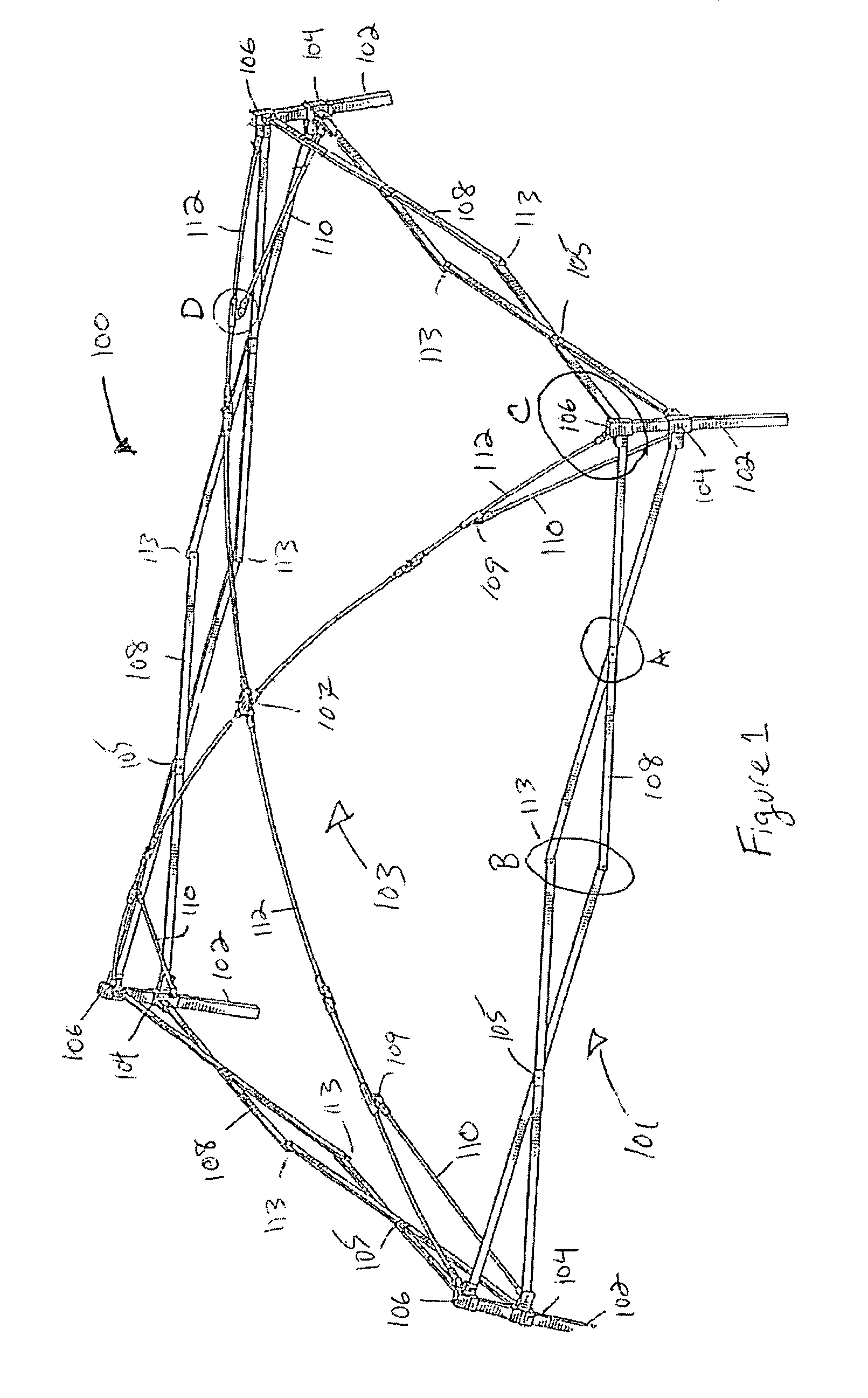
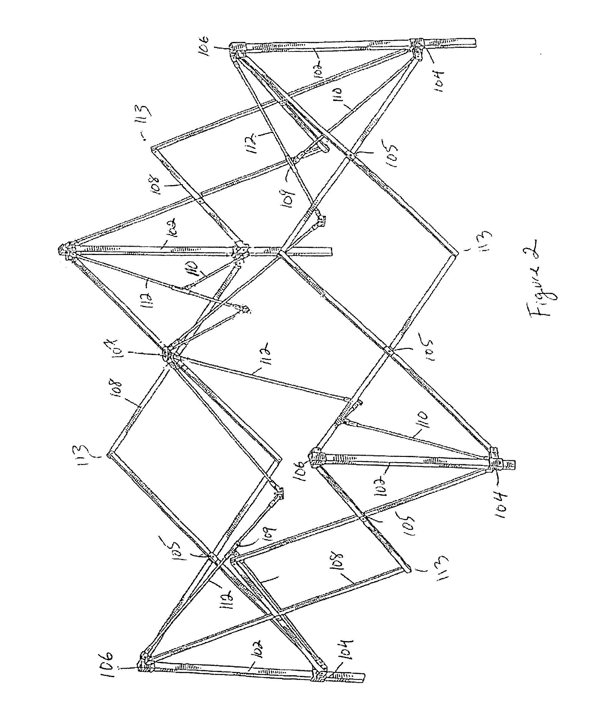
[0030]As shown by way of example in FIG. 1, a shelter frame 100 in accordance with a first preferred embodiment of the present invention includes a lower frame member 101 and a canopy support 103. The lower frame member 101 includes four upwardly extending poles 102 that are connected to one another by four pairs of scissors-type (or x-type) cross joints 105. Each of the scissor-type cross joints 105 are pivotally secured to another linkage and to one of the poles 102. The cross joints 105 are secured to the poles 102 by fixed connectors 106, which are secured to the top of each pole, and sliding connectors 104 which slide along the poles. The exemplary canopy h...


PUM


Abstract

The present invention provides an improved portable shelter frame having upwardly extending support poles and linkage assemblies connecting the poles. Within the joints of the linkage assemblies are rolling element bearings to reduce joint friction and provide reinforcement support to the shelter frame.

Description

CROSS REFERENCE TO RELATED APPLICATIONS[0001]This application claims the benefit of U.S. Provisional Application 60 / 482,503, entitled Portable Shelter Framework, filed Jun. 24, 2003, and U.S. Provisional Application 60 / 449,124 entitled Shade Structure With Roller Bearings, filed Feb. 21, 2003, both of the contents of which are hereby incorporated by reference.BACKGROUND OF THE INVENTION[0002]1. Field of Invention[0003]The present invention relates generally to shelters and, more particularly, to shelters including collapsible frames.[0004]2. Description of the Related Art[0005]Over the years, a seemingly endless variety of tents and other shelters having collapsible frames have been introduced into the market. Such structures are commonly used to provide shelter during camping trips, picnics, parties, military operations and other outdoor activities. Because their frames are collapsible, relatively large shelters may be folded into a compact configuration for storage and transport.[...

Claims


Application Information

Patent Timeline
IPC IPC(8): E04H15/50
CPCE04H15/50Y10T403/32155
Inventor LOSI, JR., RAYMOND
Owner VARIFLEX
Why Eureka
Try Eureka