
Folding container

a container and folding technology, applied in the field of containers, can solve the problems of increasing distribution costs, difficult folding of the upper and lower plate bodies of the left and right side plates, and low space utilization rate, and achieve the effects of convenient container handling, optimized space utilization, and superior durability

Inactive Publication Date: 2013-01-24
HONG JUNG SUN +1
View PDF8 Cites 15 Cited by
  • Summary
  • Abstract
  • Description
  • Claims
  • Application Information

AI Technical Summary

Benefits of technology

The present invention is a folding container that can be conveniently handled and maintained in either a folded or unfolded state. It is designed with a reliable folding means that allows for easy and convenient handling, and it is durable and safe to use. The container body is connected by spring hinges and connection brackets, which improves its durability in both vertical and horizontal directions. The cross-sectional structure of the spring wire is improved, and the number of torsion coil springs and their turns are changed depending on the load applied, which increases the durability of the container body and makes it easier to unfold.

Problems solved by technology

Therefore, the rate of use of space is low, thus increasing distribution costs.
First, to elastically unfold the upper and lower plate bodies of the left and right side plates of the container body which have been in the folded state, the elastic force of the spring hinges must be sufficiently high. However, when the elastic force of the spring hinges is high, it becomes very difficult to fold the upper and lower plate bodies of the left and right side plates due to the high elastic force of the spring hinges.
In particular, because the folding operation is manually performed by workers, it is very difficult for a small number of workers to fold the container body, thus increasing safety concerns.
Secondly, the top plate, the left and right side plates and the bottom plate of the container body are connected and fastened to each other only by spring hinges.
Thus, the elastic force of each spring hinge is not sufficient.
Therefore, a comparatively large number of spring hinges are required to smoothly unfold the container body.
Thus, a portion where the elastic durability of the torsion spring of the spring hinge weakens may occur.
However, because the torsion coil spring is twisted when the container body is folded, the legs of the torsion coil spring must move in the longitudinal direction of the spring, but the legs of the torsion coil spring cannot move.
Thus, a load applied to the torsion coil spring is increased, thus reducing the durability of the spring hinge.
In this state, when unlocking the double locking hooks to unfold the container body, because the top plate and the left and right side plates are elastically biased upwards by the elastic force of the spring hinges, it is very difficult to remove the double locking hooks from the latches.
Rather, the double locking hook may be bent and inserted between the left and right side plates, thus impeding the folding of the container body.
Sixth, when a first one of the left and right side plates of the container body which has been folded is unfolded after a second one of them is vertically unfolded, the second side plate may be bent towards the first side plate rather than being maintained in the vertical state, and the first side plate and the top plate may lean towards a worker, thus endangering the safety of the worker.
However, because the junctions between the top plate, the left and right side plates and the bottom plate of the container body have no sealing structure, the ability to seal the container body is markedly low.

Method used


Image

  • Folding container
  • Folding container
  • Folding container

Examples


Embodiment Construction

[0079]Hereinafter, a preferred embodiment of the present invention will be described in detail with reference to the attached drawings.

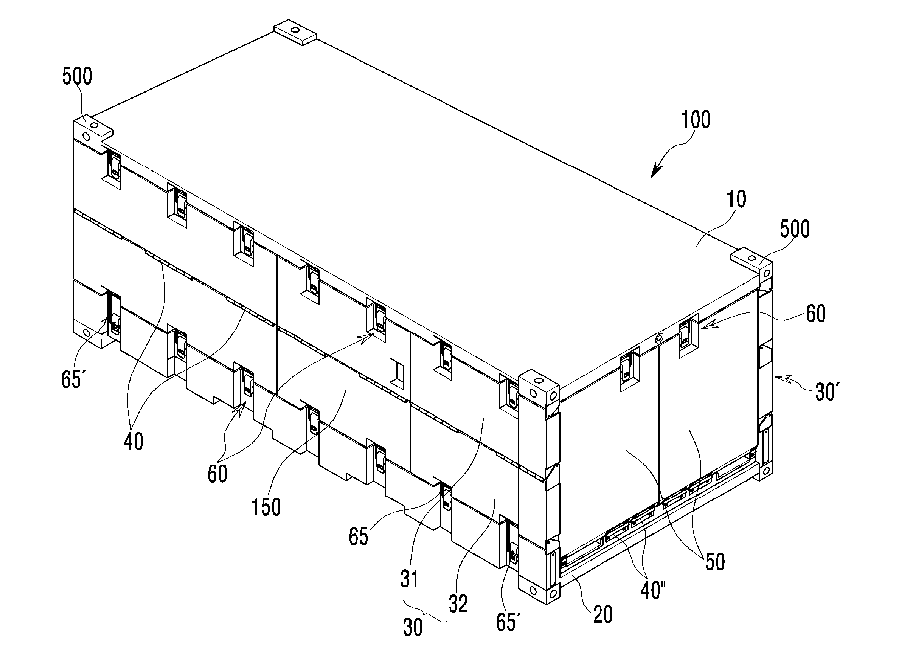
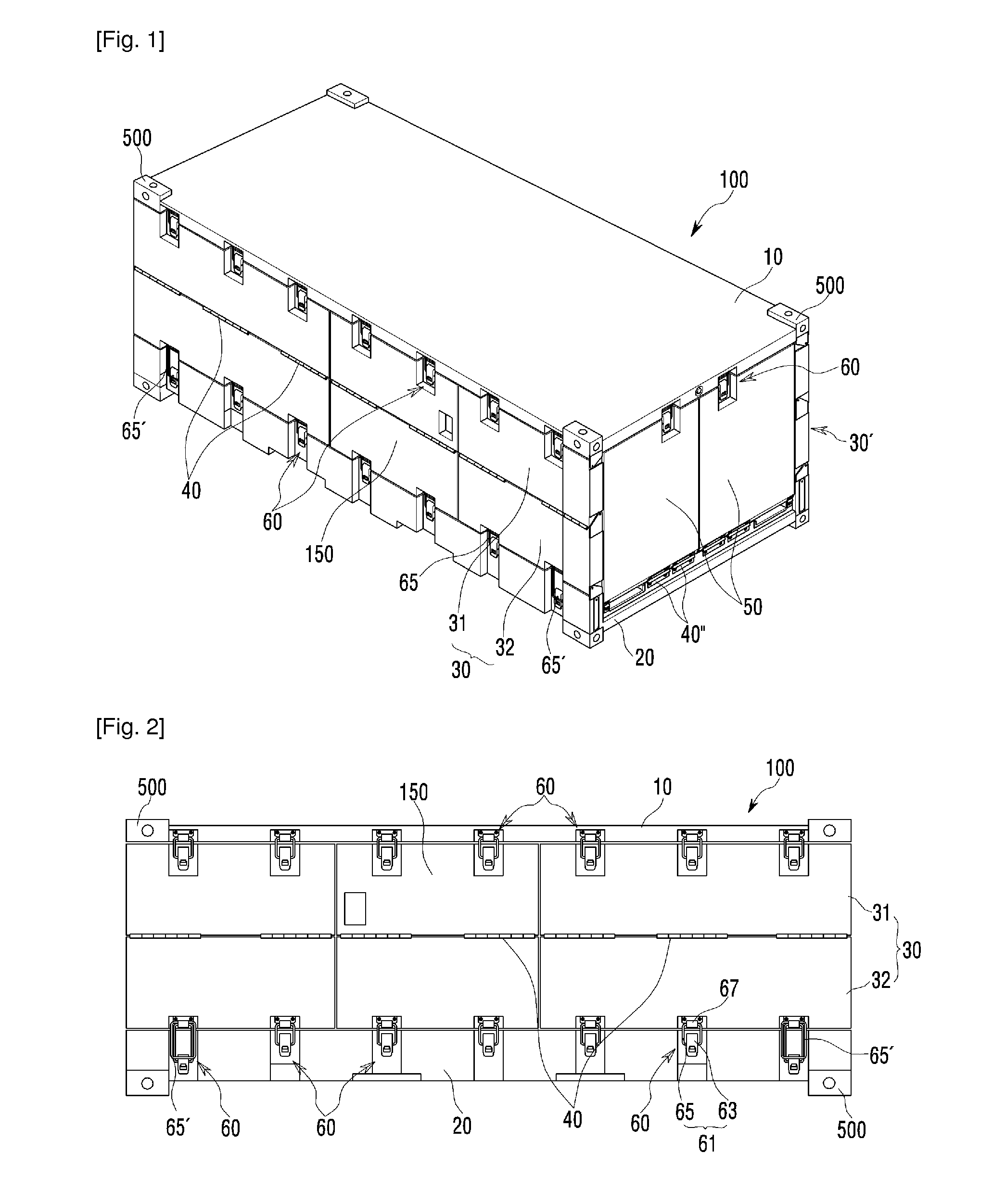
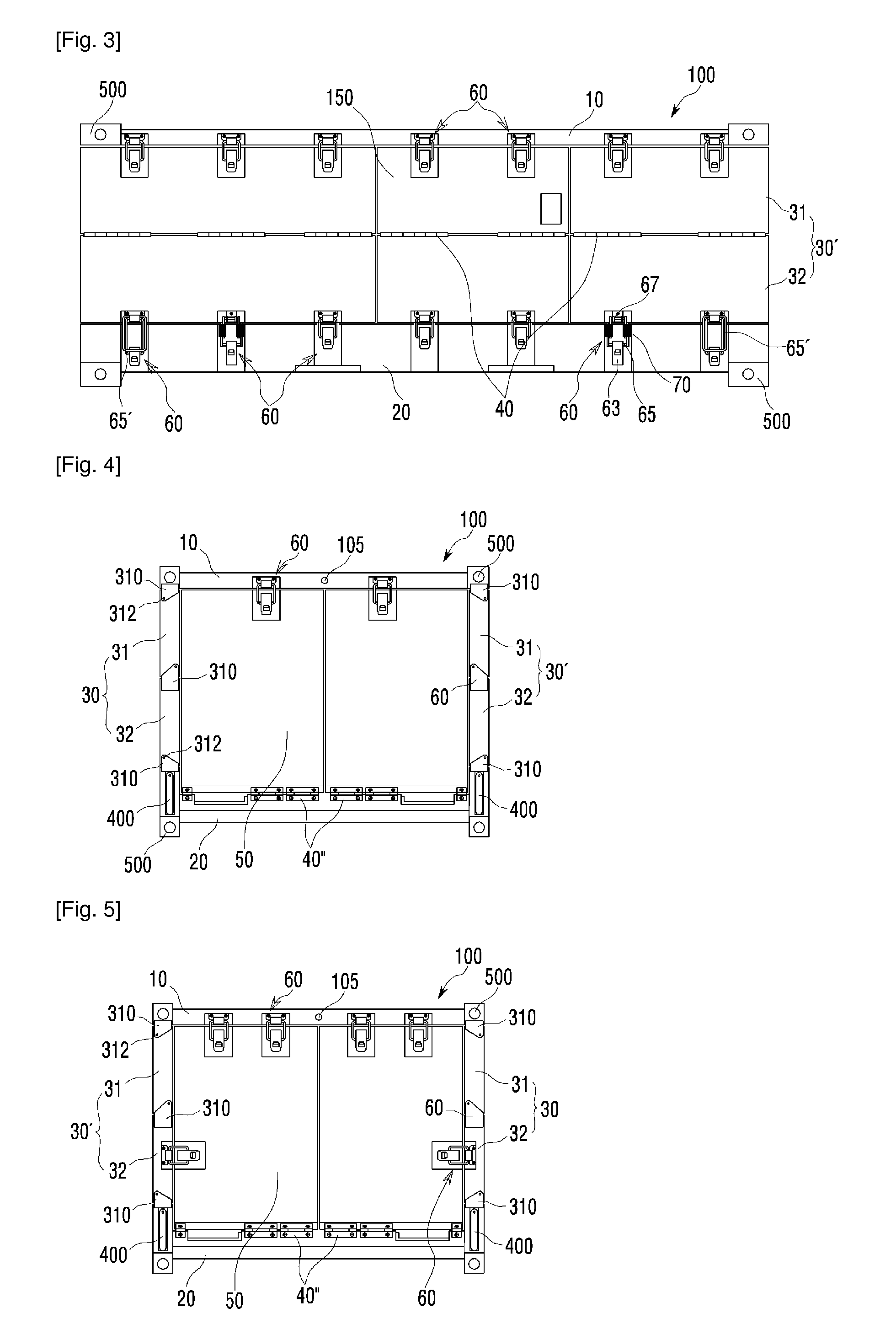
[0080]As shown in FIGS. 1 through 38, a folding container according to the present invention includes a container body 100 which defines a loading space 2 therein. The container body 100 includes a top plate 10, a bottom plate 20, left and right side plates 30 and 30′, and front and rear end plates 50 and 50′. The left and right side plates 30 and 30′ are vertically provided at opposite sides between the top plate 10 and the bottom plate 20. Each of the left and right side plates 30 and 30′ includes upper and lower plate bodies 31 and 32. The upper and lower plate bodies 31 and 32 of the left and right side plates 30 and 30′ are connected to each other and to the top and bottom plates 10 and 20 in the longitudinal direction of the container by spring hinges 40 and 40′ which are provided on an outer portion between the upper and lower plate bodies 31 ...


PUM


Abstract

Disclosed herein is a folding container which stores various kinds of cargo and is transported. A container body of the folding container includes a top plate, a bottom plate, left and right side plates, and front and rear end plates. Each side plate includes upper and lower plate bodies which are connected to each other and to the top and bottom plates by spring hinges. A rotating shaft is provided in the container body, and a belt connected to the rotating shaft is connected to the left and right side plates at positions adjacent to the junctions between the upper and lower plate bodies. The left and right side plates are pulled inwards and folded by rotating the rotating shaft and winding the belt around the rotating shaft. Therefore, the operation of folding or unfolding the container body can be facilitated, and safety can be ensured during the operation.

Description

CROSS-REFERENCES TO RELATED APPLICATION[0001]This application is a Continuation Application of U.S. patent application Ser. No. 13 / 260,370 filed Sep. 25, 2011, which is a National Stage application of PCT / KR2011 / 006510 filed on Sep. 2, 2011, which claims priority to Korean Patent Application Nos. 10-2011-0072735 filed on Jul. 22, 2011 and 20-2011-0007333 filed on August 12, 2011, the contents of which are incorporated herein by reference.BACKGROUND OF THE INVENTION[0002]1. Field of the Invention[0003]The present invention relates generally to containers which store various kinds of cargo therein and are transported by ships or the like and, more particularly, to a folding container which is configured such that a small number of workers can easily fold or unfold a container body using a folding means so that it is convenient to handle the container and the use of space is optimized, and which has a superior durability and is able to be safely used, because the container body can be ...

Claims


Application Information

Patent Timeline
Patent Type & Authority Applications(United States)
IPC IPC(8): B65D6/16
CPCB65D90/08B65D88/524
Inventor HONG, JUNG SUN
Owner HONG JUNG SUN
Learn More