Compound lift device

a technology of lifting device and weight, which is applied in the direction of machine support, furniture parts, television systems, etc., can solve the problems of insufficient stability, inability to adjust the height of the device, and inability to meet the needs of users, so as to facilitate greater height adjustment, reduce weight and cost, and minimize cabinet size

Inactive Publication Date: 2006-05-16
BOBER WIESLAW
View PDF9 Cites 85 Cited by
  • Summary
  • Abstract
  • Description
  • Claims
  • Application Information

AI Technical Summary

Benefits of technology

[0011]An object of the present invention is to provide a television lift device of telescoping design so as to provide for the compact storage of both lift and television.
[0013]The present invention is a compound motorized lift facilitating the uninterrupted and nearly noiseless movement of a low-profile television. The invention is comprised of a base unit, an intermediate unit, and a support unit slidably disposed in a telescoping fashion in the described order. A pair of linearly extensible slides are fastened between base and intermediate units and between intermediate and support units. The intermediate unit is extended and retracted from the base unit in a linear fashion via a motor driven screw. The support unit is extended and retracted in a linear fashion via a cable-pulley arrangement that couples movement of the intermediate unit to the support unit in a likewise direction.
[0021]Several advantages are offered by the present invention. The invention minimizes cabinet size thereby reducing weight and cost. The invention enables both extension and retraction of a low-profile television in a smooth, stable, and nearly noiseless fashion. The invention facilitates greater height adjustability thereby accommodating a variety of viewing conditions.

Problems solved by technology

However, designs are inherently less decorative, less stable, and heavier than conventional televisions.
While lifts are known within the art, the height of such devices greatly exceeds that of the low-profile television.
As such, cabinet dimensions are dictated by the lift envelope rather than by the size of the television thereby favoring volumetrically inefficient designs.
Furthermore, such cabinets place the television at a height that is less than optimal for viewing conditions within residential settings.

Method used


Image

  • Compound lift device
  • Compound lift device
  • Compound lift device

Examples


Embodiment Construction

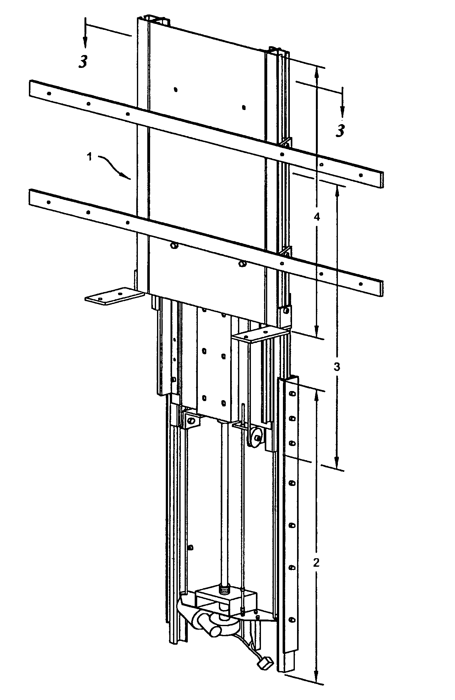
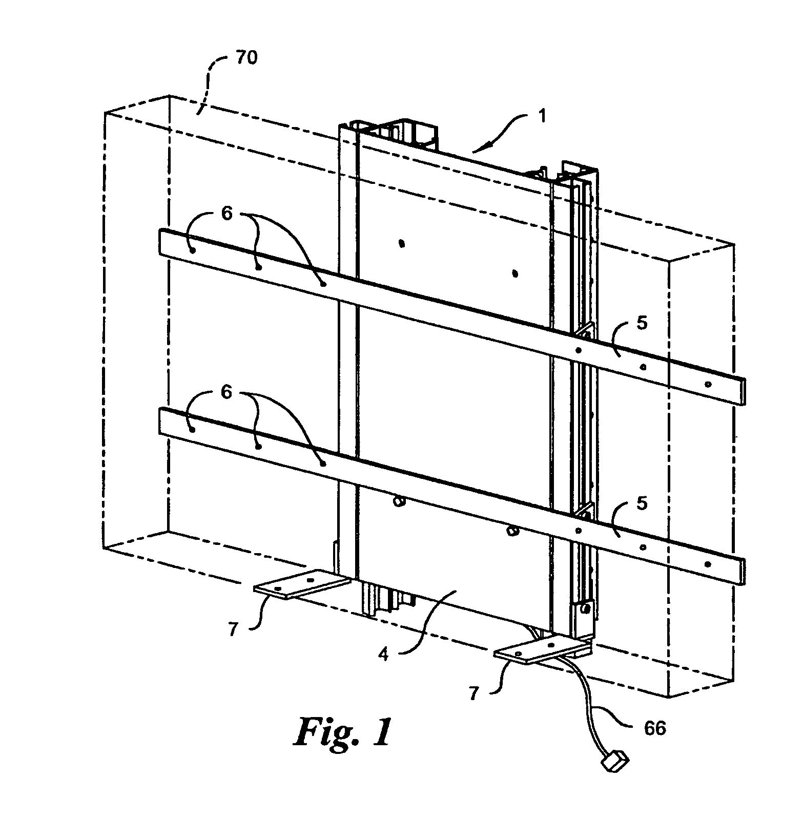
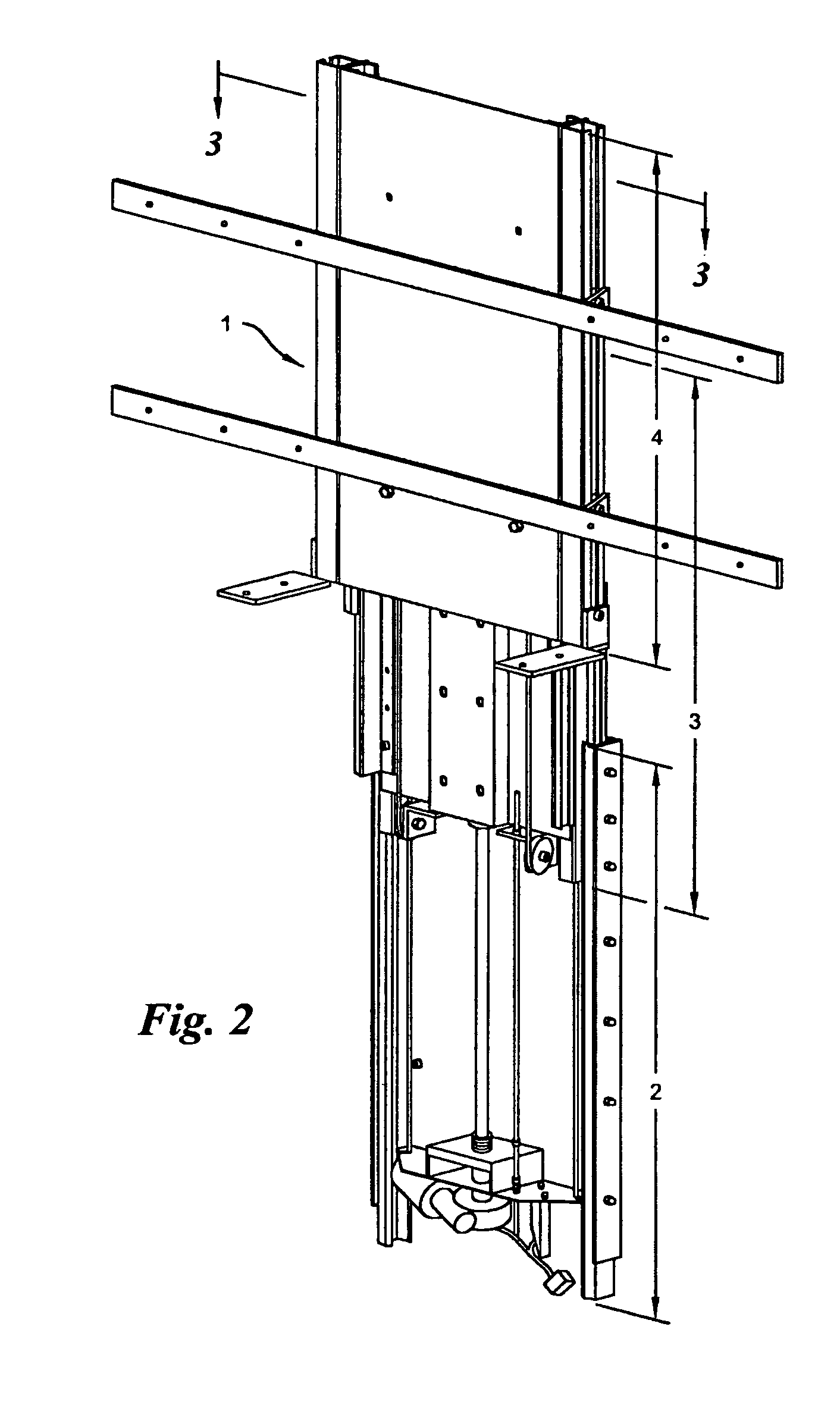
[0117]Referring now to FIG. 1, an exemplary embodiment of the present invention, namely a compound lift 1 capable of extending and retracting a low-profile display 70, is shown in its retracted position wherein a support unit 4, an intermediate unit 3, and a base unit 2 of comparable lengths are arranged in a telescoping-like fashion so as to conceal the intermediate unit 3 behind support unit 4 and base unit 2 behind intermediate unit 3. FIG. 2 shows the same compound lift 1 having both support unit 4 and intermediate unit 3 extended from the base unit 2. The present invention may be mechanically attached to a storage cabinet via methods and techniques understood in the art.

[0118]A variety of application are possible for the present invention. For example, the compound lift 1 may raise a low-profile display 70 above or lower a low-profile display 70 below a cabinet in a vertical fashion. Likewise, the compound lift 1 may extend a low-profile display 70 in a horizontal fashion from ...


PUM


Abstract

The present invention is a compound motorized lift device facilitating the uninterrupted and nearly noiseless movement of a low-profile television. The invention is comprised of a base unit, an intermediate unit, and a support unit slidably disposed in a telescoping fashion in the described order. A pair of linearly extensible slides are fastened between base and intermediate units and between intermediate and support units. The intermediate unit is extended and retracted with respect to the base unit in a linear fashion via a motor driven screw. The support unit is extended and retracted in a linear fashion via a cable-pulley arrangement that couples motion by the intermediate unit in a likewise direction to the support unit.

Description

CROSS REFERENCE TO RELATED APPLICATIONS[0001]None.FEDERALLY SPONSORED RESEARCH OR DEVELOPMENT[0002]None.BACKGROUND OF THE INVENTION[0003]1. Field of the Invention[0004]The present invention generally relates to a motorized lift. Specifically, the invention is a compound lift capable of extending a low-profile television from and retracting a low-profile television into a storage cabinet so as to provide volume efficient storage.[0005]2. Description of the Related Art[0006]Television design trends are now focused on low-profile devices including but not limited to plasma screens and LCD panels. Low-profile televisions maximize viewing area and minimize unit depth. However, designs are inherently less decorative, less stable, and heavier than conventional televisions.[0007]Aesthetic and stability deficiencies of low-profile televisions are addressed by housing the television within a cabinet. In such applications, the low-profile television is extended from and retracted into the cabi...

Claims


Application Information

Patent Timeline
Patent Type & Authority Patents(United States)
IPC IPC(8): F16M11/00A47B81/06F16M11/18F16M11/24
CPCA47B81/064F16M11/18F16M11/30F16M11/046F16M11/24A47B2200/04H04N5/64
Inventor BOBER, WIESLAWREPELEWICZ, JOZEFMALEK, JOZEFSMIESZEK, WLODZIMIERZ
Owner BOBER WIESLAW
Why Eureka
Try Eureka