Lock bars for blowout preventer

a technology of lock bars and preventers, which is applied in the direction of sealing/packing, borehole/well accessories, transportation and packaging, etc., can solve the problems of damage to seals, and achieve the effect of being easily moved to a deployed position

Active Publication Date: 2006-05-16
VARCO I P INC
View PDF27 Cites 45 Cited by
  • Summary
  • Abstract
  • Description
  • Claims
  • Application Information

AI Technical Summary

Benefits of technology

[0014]In one aspect, a block support according to the present invention has a plurality of pivotably connected parts providing an articulable support that is easily movable to a deployed position.

Problems solved by technology

Such seals can be subject to high pressures and to chemical reaction with drilling fluids which can damage the seals.

Method used


Image

  • Lock bars for blowout preventer
  • Lock bars for blowout preventer
  • Lock bars for blowout preventer

Examples


Embodiment Construction

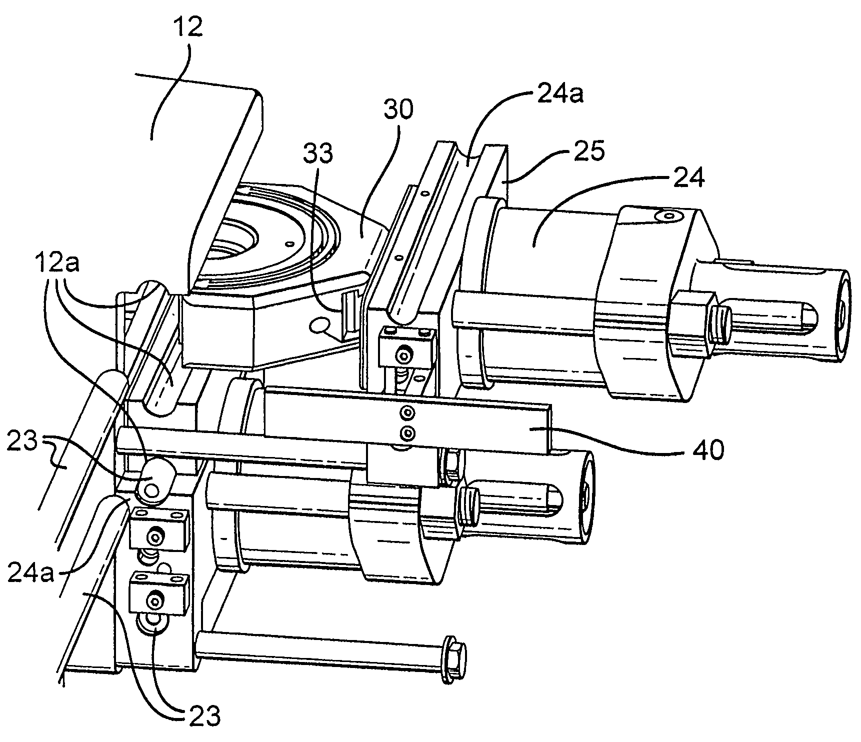
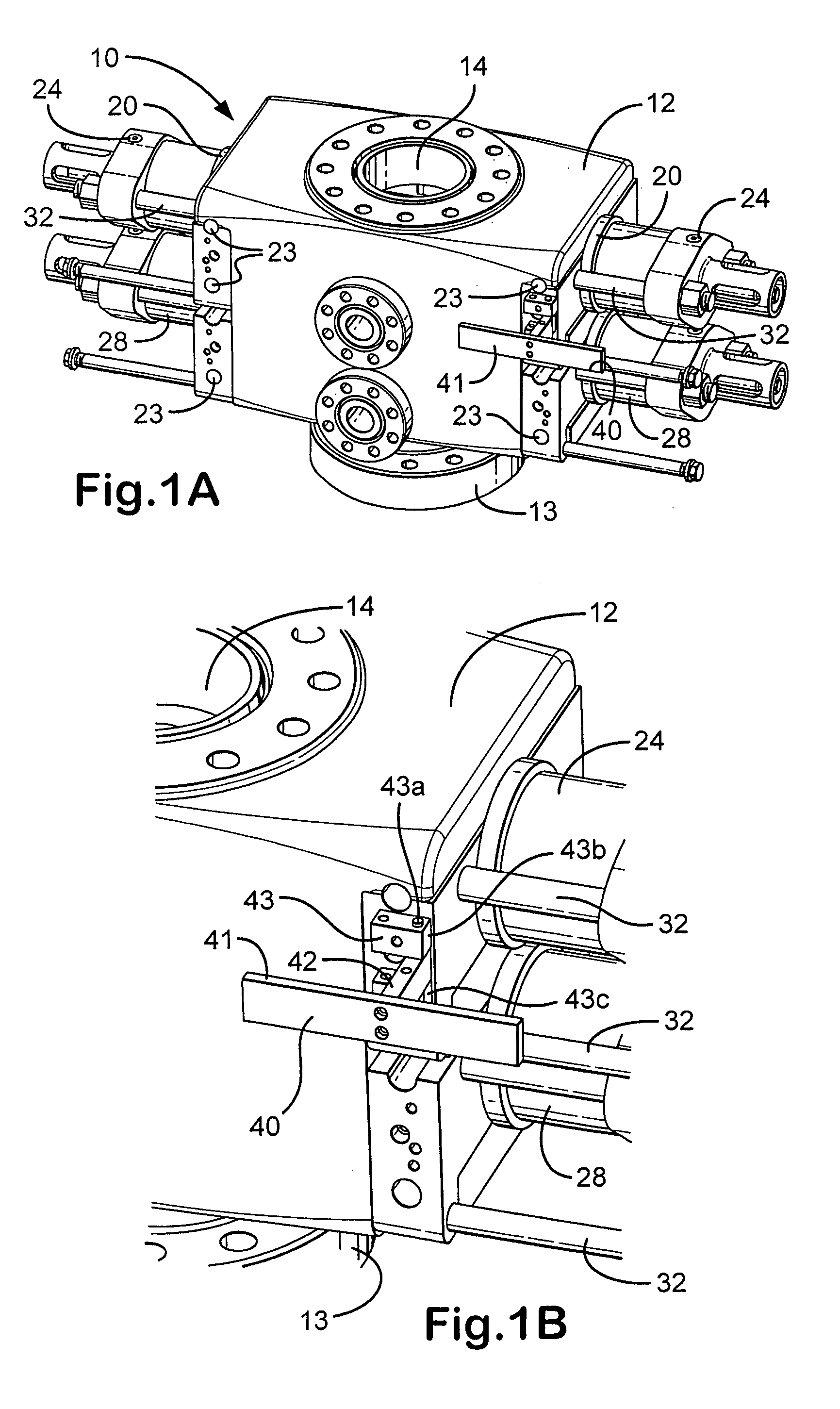
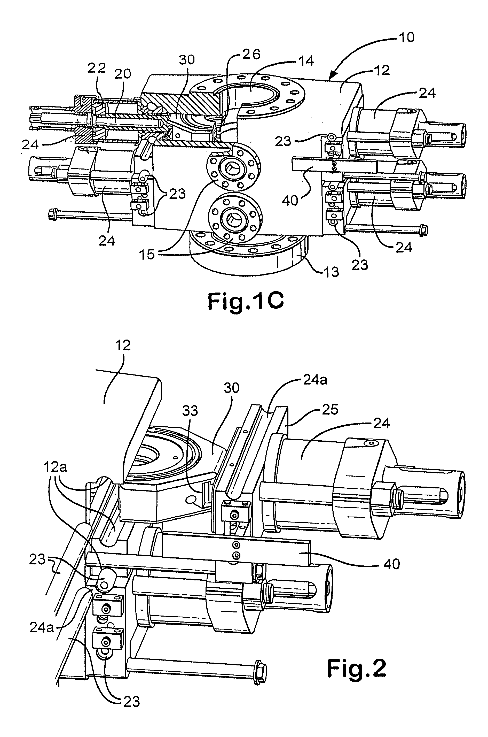
[0028]As shown in FIGS. 1A–1C a blowout preventer 10 according to the present invention has a main body 12 with a bore 14 therethrough from top to bottom, side outlets 15, and a lower flange 13 for releasably connecting the blowout preventer 10 to other apparatus, e.g. in a wellhead installation.

[0029]The blowout preventer 10 has opposed ram apparatuses 20 each with its respective actuator apparatus 22 within a bonnet 24. Each ram apparatus 20 includes a typical ram block 30 with seals 26. Below the bonnets 24 are dual opposed bonnets 28 each housing rams (not shown) and associated actuator apparatuses.

[0030]It is within the scope of the present invention for the bonnets 24 to be movably connected to the main body 12 in any manner with any structure known in the prior art. As shown in FIGS. 1 and 2 the bonnets are releasably connected to the main body 12 with removable bars 23, according to the present invention, and the bonnets 24 are movably mounted on shafts 32 which project out ...


PUM


Abstract

Lock bars for blowout preventers and blowout preventers having, in certain aspects, a body with a top, a bottom, and a bore therethrough, at least one bonnet releasably secured to the body, a first lock bar recess defined by a first portion in the body and a second portion in the bonnet, at least one lock bar removably disposed in the lock bar recess for releasably connecting the at least one bonnet to the body, the at least one lock bar having a body with a first end and a second tapered end and / or with an end opening in an end of the at least one lock bar.

Description

CROSS REFERENCE TO RELATED APPLICATIONS[0001]This is a division of U.S. application Ser. No. 10 / 836,819 filed Apr. 30, 2004, fully incoroporated herein for all purposes.BACKGROUND OF THE INVENTION[0002]1. Field of the Invention[0003]This present invention is directed to blowout preventers, to bonnets and ram blocks for them, and, in certain particular aspects, to pivotal ram block supports, and methods of their use.[0004]2. Description of Related Art[0005]The prior art discloses a wide variety of blowout preventers and blowout preventer bonnets.[0006]Typical blowout preventers have selectively actuatable rams in oppositely disposed bonnets secured to the body which, in certain prior art systems, are movably secured with movable bars or with hinges and bolts so that the bonnet is movable for access and maintenance. The rams are either pipe rams (to contact, engage, and encompass pipe and / or tools to seal a wellbore) or shear rams (to contact and physically shear a pipe or tool in a w...

Claims


Application Information

Patent Timeline
Patent Type & Authority Patents(United States)
IPC IPC(8): F16K51/00E21B33/06
CPCE21B33/062Y10T137/7069
Inventor BRUGMAN, JAMES D.SPRINGETT, FRANK BENJAMINBENNETT, DEAN ALLEN
Owner VARCO I P INC
Why Eureka
Try Eureka