Night vision system and control method thereof

a technology of night vision and control method, applied in the field of night vision system, can solve problems such as difficulty in distinguishing subjects, and achieve the effect of reducing the brightness and the degree of halation

Inactive Publication Date: 2006-05-16
DENSO CORP +1
View PDF11 Cites 3 Cited by
  • Summary
  • Abstract
  • Description
  • Claims
  • Application Information

AI Technical Summary

Benefits of technology

The invention is a night vision system that prevents bright subjects from being obscured by darker ones in an image. This is achieved by producing a gamma correction signal based on a brightness ratio characteristic, which determines the display brightness based on the maximum and minimum brightness levels of the image. The result is that all regions of the image, each with different levels of brightness, can be appropriately displayed without halation. The control method involves setting the display brightness to a maximum level using an equi-proportional display brightness correction ratio when the brightness signal is at its maximum level, and then adjusting the display brightness using a lower brightness correction ratio when the brightness signal is lower. This reduces the degree of halation around the highest brightness subjects and makes other subjects with lower brightness appear more distinguishable.

Problems solved by technology

With conventional displays, however, when the brightness of a subject desired to clearly appear on the screen is lower than the brightness of a region surrounding the subject or the brightness of other subjects located in the vicinity thereof, it is difficult to distinguish that subject due to the brightness of its periphery, namely due to the halation.

Method used


Image

  • Night vision system and control method thereof
  • Night vision system and control method thereof
  • Night vision system and control method thereof

Examples


Embodiment Construction

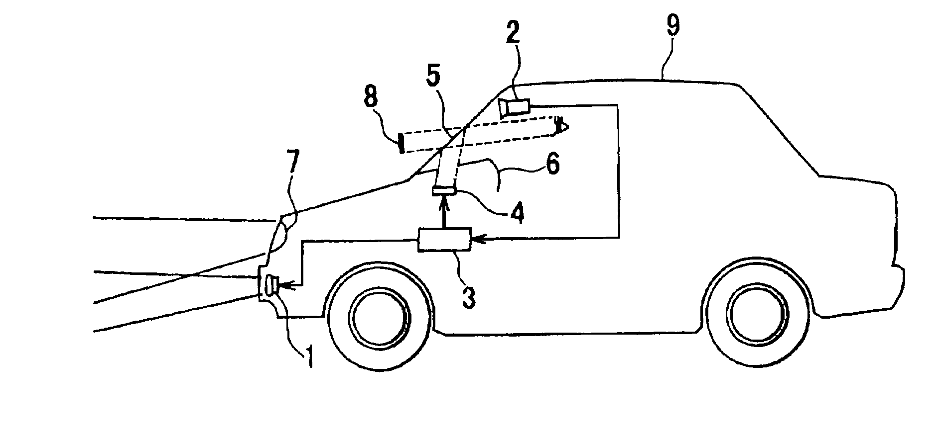
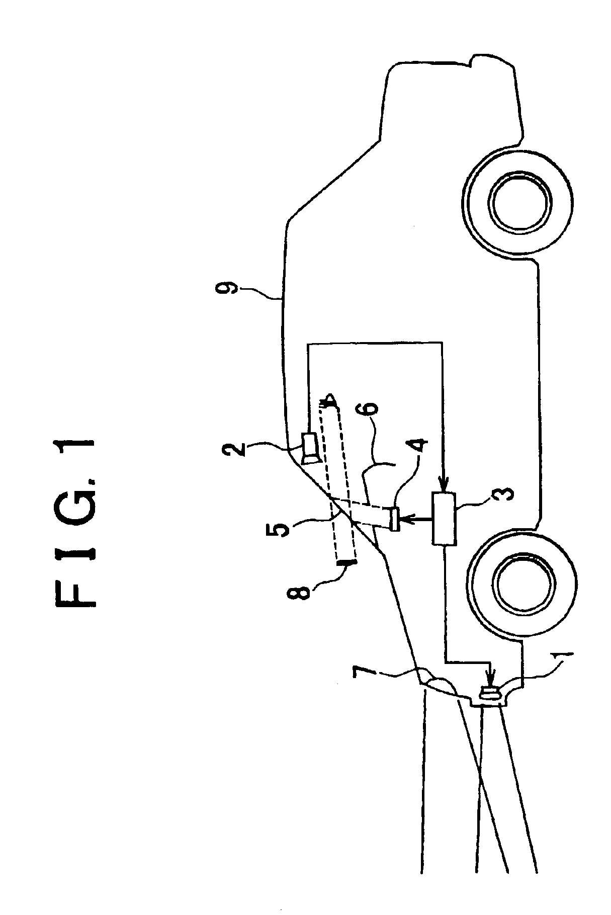
[0018]A preferred embodiment of the invention will hereinafter be described with reference to the accompanying figures. FIG. 1 schematically shows the construction of a night vision system according to the embodiment when it is applied to a head-up display system for vehicles. This night vision system includes a near-infrared lamp 1, camera 2, night vision control circuit (will hereinafter be referred to as “ECU”) 3, liquid crystal display (will hereinafter be referred to as “LCD”) 4 serving as a display device, and combiner portion 5.

[0019]The near-infrared lamp 1 is disposed in a front bumper of a vehicle 9 and is operated to project a near-infrared light including a light having a wavelength of 800 to 1000 mm in a forward direction of the vehicle 9. The camera 2 is adapted to receive the light from subjects, namely an image formed by the near-infrared light reflected from the subject, and output the captured image in the form of image signals.

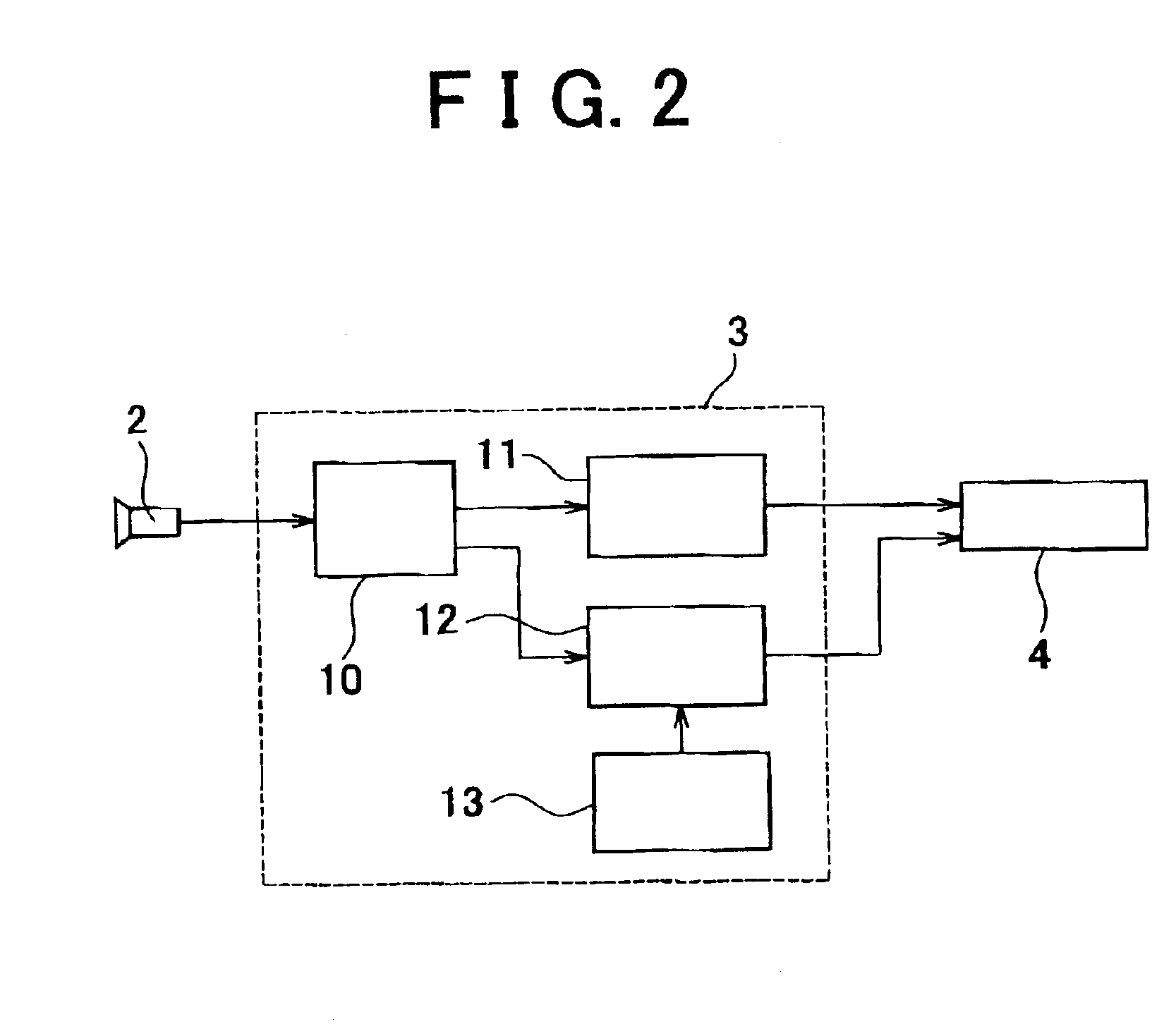
[0020]In operation, the ECU 3 process...


PUM


Abstract

A second circuit separately extracts a synchronization signal and brightness signal from an image signal output from a camera for capturing an image of a subject. A gamma amplifier produces a gamma correction signal based on a brightness ratio characteristic in which a display brightness increases as the signal level of the brightness signal increases and the display brightness is set using a display brightness correction ratio which is preferably 70 to 90% of an equi-proportional display brightness correction ratio when the signal level of the brightness signal falls in a high-brightness range. A liquid crystal display receives the gamma correction signal and displays an image captured by the camera with the display brightness set in accordance with the brightness ratio characteristic while synchronizing with a drive timing signal output from a first circuit. Thus, the difference in display brightness between different high-brightness regions or subjects is made large, whereby halation which may otherwise occur between those regions or subjects can be prevented.

Description

INCORPORATION BY REFERENCE[0001]The disclosure of Japanese Patent Application No. 2002-051447 filed on Feb. 27, 2002, including the specification, drawings and abstract is incorporated herein by reference in its entirety.BACKGROUND OF THE INVENTION[0002]1. Field of Invention[0003]The invention relates to a night vision system and a control method thereof.[0004]2. Description of Related Art[0005]There is known a so-called night vision system which captures an image of a subject by receiving infrared lights projected from the night vision system and reflected by the subject or infrared lights emitted from the subject by means of an infrared camera and which displays the captured image on a display. Using infrared lights, such a night vision system is able to reliably capture images, and is therefore expected to be widely used as a driving assistance system for motor vehicles, and the like, for improving the visibility at night. With conventional displays, however, when the brightness ...

Claims


Application Information

Patent Timeline
Patent Type & Authority Patents(United States)
IPC IPC(8): H01J40/14B60R21/00B60R11/04H04N5/66H04N7/18H04N23/76
CPCH04N5/202H04N5/243H04N5/2354H04N23/76H04N23/74H04N23/21H04N23/82
Inventor HARA, YOSHIMASAEGUCHI, SHOTAROHAGISATO, YASUOYAMAGUCHI, RYUJITOYOFUKU, KUNIHIKOKAWAMATA, SHINYA
Owner DENSO CORP
Why Eureka
Try Eureka