
Method and apparatus for self servowriting of tracks of a disk drive using an observer based on an equivalent one-dimensional state model

a disk drive and observer technology, applied in the field of magnetic disk drives, can solve the problems of radial error propagation and amplification, and the filtering technique of the yarmchuk patent fails to readily support increasingly aggressive track densities, so as to reduce radial error propagation

Inactive Publication Date: 2006-05-16
WESTERN DIGITAL TECH INC
View PDF11 Cites 113 Cited by
  • Summary
  • Abstract
  • Description
  • Claims
  • Application Information

AI Technical Summary

Benefits of technology

The present invention relates to a method and apparatus for writing servo patterns on a rotating magnetic disk medium. The method involves track following along a reference track using a servo loop with a closed-loop response. A position error signal is generated based on the track following, and a correction signal is generated based on the track following using an observer of a one-dimensional state model. The position error signal of the servo loop is adjusted based on the correction signal to reduce radial error propagation from the reference track to the target track. The invention allows for precise positioning of the servo patterns, improving the accuracy and reliability of the magnetic disk drive.

Problems solved by technology

One issue confronting the use of self servowriting is track-to-track or radial error propagation and amplification of written-in errors and imperfections with respect to a perfectly circular track.
While permitting implementation of self servowriting with reduced radial error propagation, the PES filtering technique of the Yarmchuk patent fails to readily support increasingly aggressive track densities.

Method used


Image

  • Method and apparatus for self servowriting of tracks of a disk drive using an observer based on an equivalent one-dimensional state model
  • Method and apparatus for self servowriting of tracks of a disk drive using an observer based on an equivalent one-dimensional state model
  • Method and apparatus for self servowriting of tracks of a disk drive using an observer based on an equivalent one-dimensional state model

Examples


Embodiment Construction

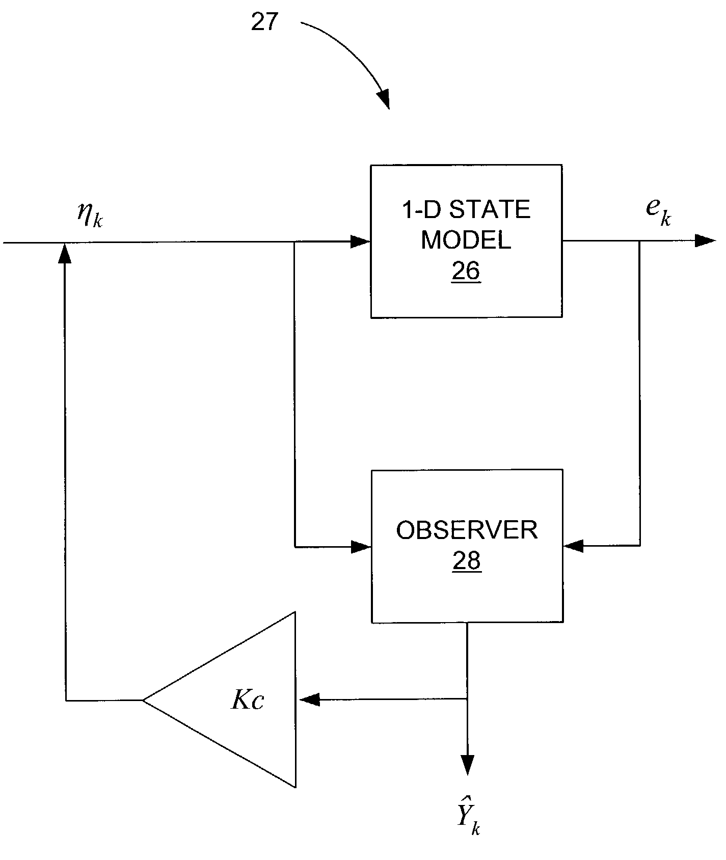
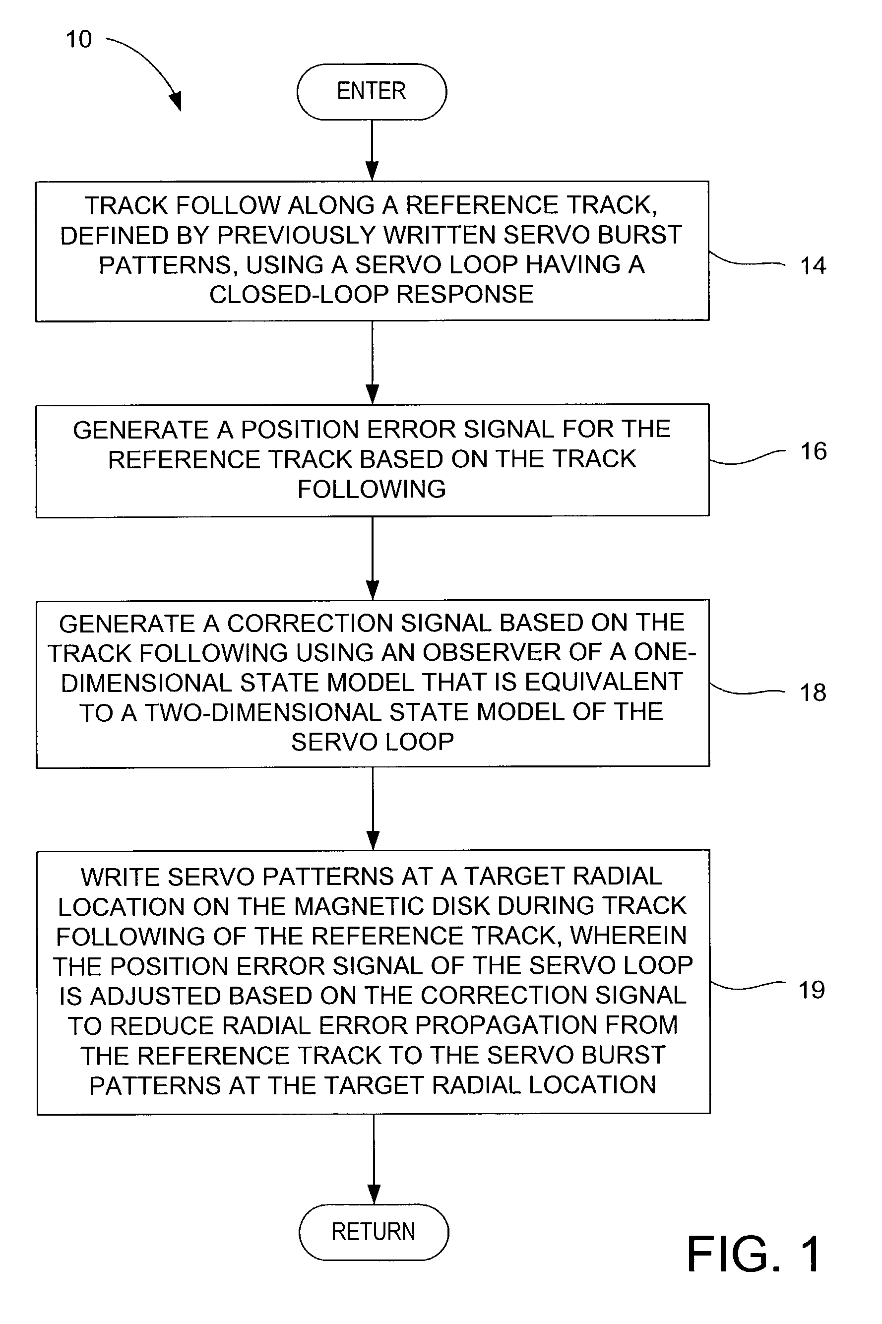
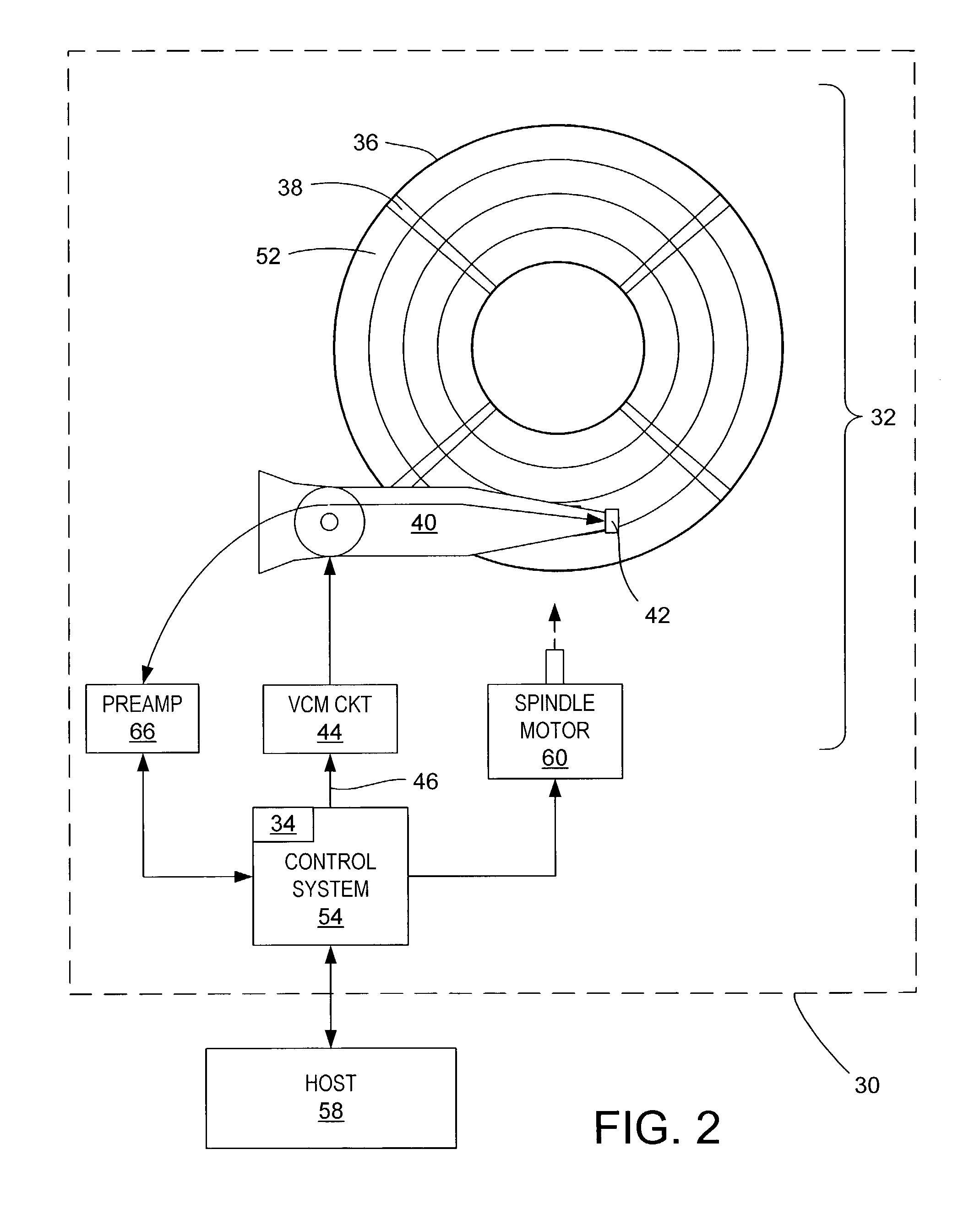
[0021]With reference to FIGS. 1 through 5, the present invention may be embodied in a method 10 (FIG. 1), implemented in the disk drive 30 (FIG. 2), for writing servo patterns A–D (FIG. 3) for tracks 12 on a rotating magnetic disk medium. In the method, track following is performed along a reference track N, defined by previously written servo burst patterns, A and B, using a servo loop 22 (FIG. 4) having a closed-loop response (step 14). A position error signal PES is generated for the reference track based on the track following (step 16). A correction signal ηk(t) is generated based on the track following using an observer 28 (FIG. 5) of a one-dimensional state model 26 that is equivalent to the two-dimensional state model of the servo loop (step 18). Servo patterns D are written at a target radial location on the magnetic disk medium during track following of the reference track (step 19). The position error signal of the servo loop is adjusted based on the correction signal to ...


PUM

PropertyMeasurementUnit
dimensionsaaaaaaaaaa
densitiesaaaaaaaaaa
frequenciesaaaaaaaaaa

Abstract

A method is disclosed for writing servo patterns for tracks on a rotating magnetic disk medium of a magnetic disk drive. In the method, track following is performed along a reference track, defined by previously written servo burst patterns, using a servo loop having a closed-loop response. A position error signal is generated for the reference track based on the track following. A correction signal is generated based on the track following using an observer of a one-dimensional state model that is equivalent to the two-dimensional state model of the servo loop. Servo patterns are written at a target radial location on the magnetic disk medium during track following of the reference track. The position error signal of the servo loop is adjusted based on the correction signal to reduce radial error propagation from the reference track to the servo burst patterns at the target radial location.

Description

[0001]This application is a continuation-in-part of application Ser. No. 10 / 232,640, filed Aug. 30, 2002, now U.S. Pat. No. 6,924,961, incorporated herein by reference.BACKGROUND OF THE INVENTION[0002]1. Field of the Invention[0003]The present invention relates to magnetic disk drives, and more particularly, to self servowriting of tracks on a rotating magnetic disk medium.[0004]2. Description of the Prior Art and Related Information[0005]The writing of servotrack information on a magnet disk medium is a critical process in the manufacture of a disk drive. Conventionally, servotrack information is written with a specialized servowriting instrument mounted on a large granite block to minimize external vibration effects. Increasing track densities and decreasing disk-drive size has led to the investigation of self servowriting techniques. One issue confronting the use of self servowriting is track-to-track or radial error propagation and amplification of written-in errors and imperfec...

Claims


Application Information

Patent Timeline
Patent Type & Authority Patents(United States)
IPC IPC(8): G11B5/596
CPCG11B5/59633G11B5/59655
Inventor MELKOTE, HEMANTCLOKE, ROBERT L.AGARWAL, VINAY K.
Owner WESTERN DIGITAL TECH INC
Learn More