
Method and apparatus for accumulating and distributing traffic and flow control information in a packet switching system

a packet switching system and flow control technology, applied in data switching networks, frequency-division multiplexes, instruments, etc., can solve problems such as the inability of receivers to have the complete and timely information necessary to make flow control decisions, the inability of receivers to identify congestion, and the inability to collect and distribute traffic and flow control information

Inactive Publication Date: 2006-05-16
CISCO TECH INC
View PDF49 Cites 20 Cited by
  • Summary
  • Abstract
  • Description
  • Claims
  • Application Information

AI Technical Summary

Benefits of technology

The patent describes a way to collect traffic information in a packet switching system and determine the traffic conditions. This is done by assigning each element in the system a unique offset value, and transmitting only a portion of the collected information to another element based on its offset value. The second element then manipulates the information to determine the traffic conditions. The technical effect of this method is to enable efficient and accurate detection and analysis of traffic in a packet switching system.

Problems solved by technology

Under certain circumstances and typically for a limited duration, these switching systems can have internal congestion as well as congestion at the output ports.
However, when a packet switch is interposed between a sender and receiver, the receiver may no longer have the complete and timely information necessary to make such flow control decisions, especially when the congestion is within the interposed packet switch.
This problem of identifying congestion is compounded when packets belonging to the same information stream are distributed among multiple paths and switching elements within the packet switching system.

Method used


Image

  • Method and apparatus for accumulating and distributing traffic and flow control information in a packet switching system
  • Method and apparatus for accumulating and distributing traffic and flow control information in a packet switching system
  • Method and apparatus for accumulating and distributing traffic and flow control information in a packet switching system

Examples


Embodiment Construction

[0022]Methods and apparatus are disclosed for accumulating and distributing traffic and flow control information in a packet switching system. Such methods and apparatus are not limited to a single packet switching environment. Rather, the architecture and functionality taught herein are extensible to an unlimited number of packet switching environments and embodiments in keeping with the scope and spirit of the invention. Embodiments described herein include various elements and limitations, with no one element or limitation contemplated as being a critical element or limitation. Each of the claims individually recite an aspect of the invention in its entirety. Moreover, some embodiments described may include, inter alia, systems, integrated circuit chips, methods, and computer-readable medium containing instructions. The embodiments described hereinafter embody various aspects and configurations within the scope and spirit of the invention.

[0023]As used herein, the term “packet” r...


PUM


Abstract

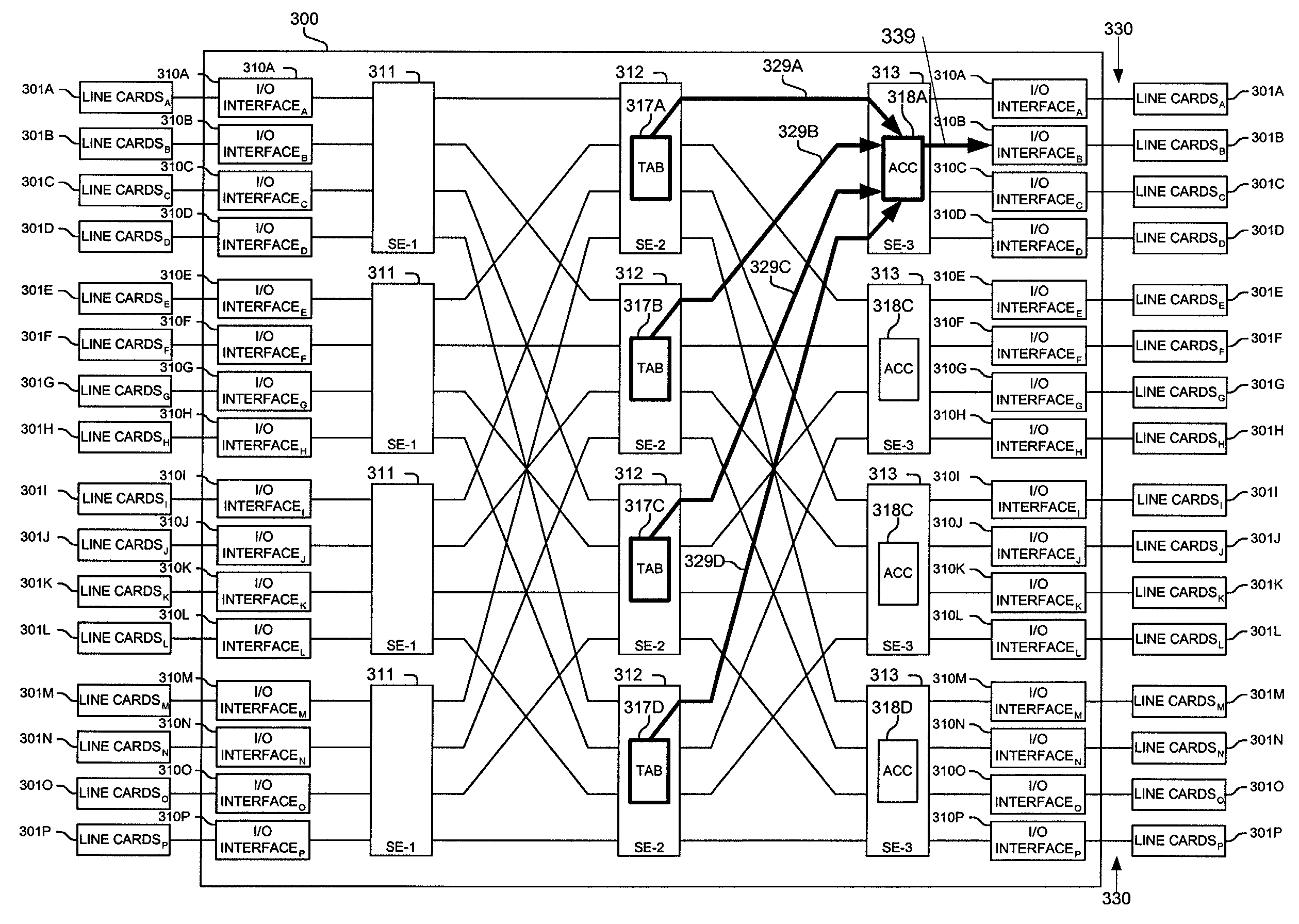
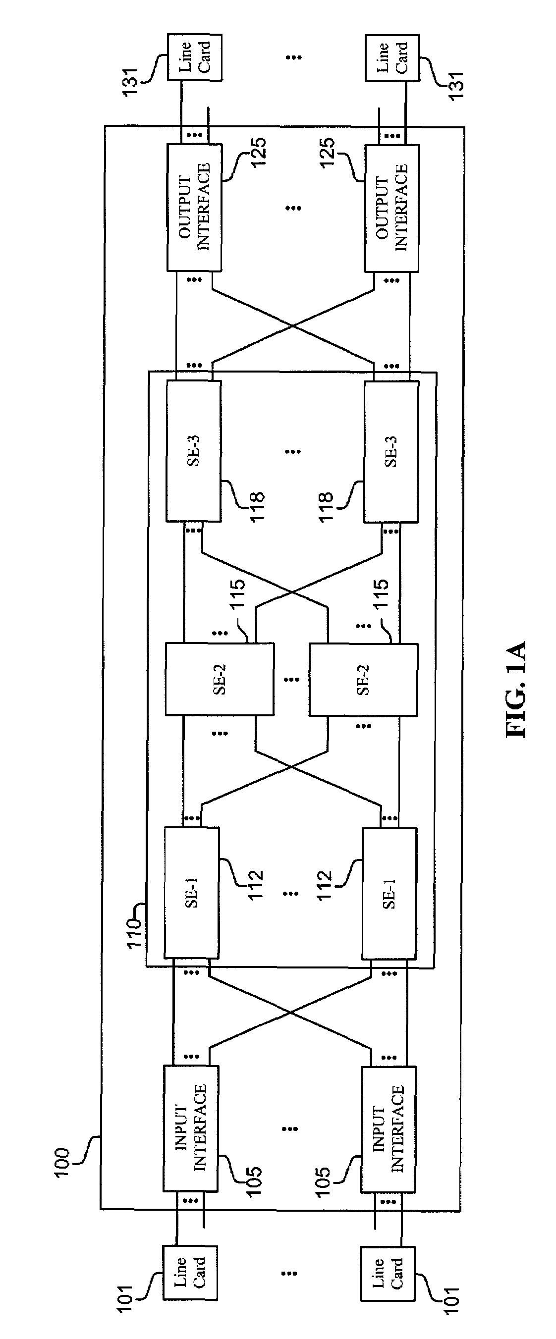
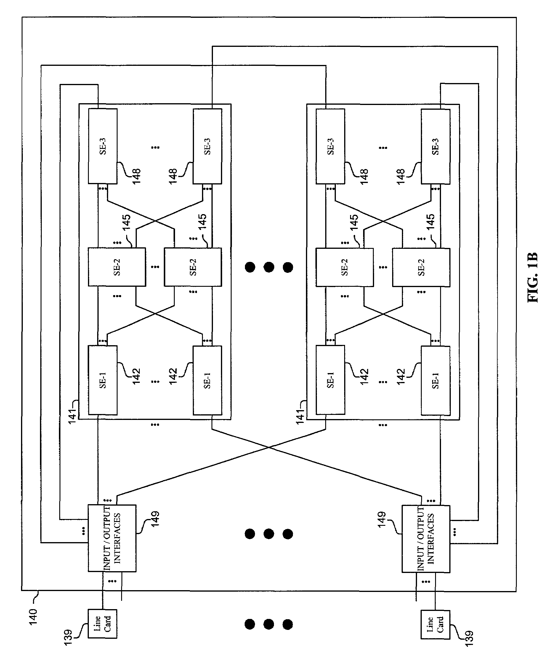
Traffic information is accumulated and flow control information distributed in a packet switching system. Traffic information is collected in multiple elements, which forward in a coordinated fashion to collecting elements indications of congestion and other types of information. The collecting elements manipulate the received indications and generate flow control messages which are sent to individual sending components of the packet switching system. In one implementation, a switching element maintains for each destination a count of packets within itself which are addressed to the particular destination. An indication of a portion of this collected information is included in a packet header forwarded from each of the elements each packet time. Each of the elements are assigned a different offset, such that they send an indication of a different portion of their collected information, so a view of the traffic conditions and / or buffer occupancies within a packet switching system is efficiently produced.

Description

CROSS-REFERENCE TO RELATED APPLICATIONS[0001]This is a continuation-in-part of copending nonprovisional application Ser. No. 09 / 784,787, filed Feb. 15, 2001, which is hereby incorporated by reference.FIELD OF THE INVENTION[0002]This invention relates to collecting and distributing traffic and flow control information in a packet switching system; and more particularly, the invention relates to collecting and accumulating traffic information in packet switch components and propagating flow control messages based on the accumulated information.BACKGROUND OF THE INVENTION[0003]The communications industry is rapidly changing to adjust to emerging technologies and ever increasing customer demand. This customer demand for new applications and increased performance of existing applications is driving communications network and system providers to employ networks and systems having greater speed and capacity (e.g., greater bandwidth). In trying to achieve these goals, a common approach take...

Claims


Application Information

Patent Timeline
Patent Type & Authority Patents(United States)
IPC IPC(8): G08C15/00H04J1/16H04J3/14H04J3/00
CPCH04L49/506H04L49/501H04L49/101
Inventor DEJANOVIC, THOMASMAUNDER, ANURAG SINGHWILLIAMS, JR., JOHN J.
Owner CISCO TECH INC
Learn More